
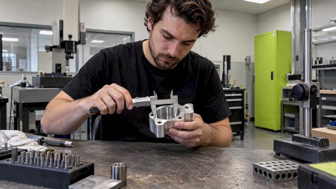
Machined part inspection is the process of measuring a finished or in-progress part and comparing the result with the nominal values and tolerances on the drawing. Done well, it answers three questions: what to check, when to check it, and with which tool. This guide walks through all three, with the reasoning a machinist uses at the machine and an engineer uses on the print.
TL;DR
- Inspection compares actual measurements with nominal design values and GD&T requirements. Conforming parts stay inside the specified tolerance limits.
- Check at several points: the first piece, in-process on features that drift, and the finished part before shipping.
- Pick the tool from the feature, the tolerance, the datums and how accessible the surface is. Calipers, micrometers, bore gauges, go/no-go gauges, CMMs and scanners each have a job.
- The gauge has to be good enough for the tolerance, and record actual values, not just pass or fail.
- Inspection results are only useful if they feed back into the process.
What machined part inspection actually checks
NIST defines inspection as measuring an actual machined part and comparing its dimensional and GD&T characteristics with nominal design values. A part conforms when those characteristics fall within the specified tolerance limits (NIST IR 8127). The same report notes that quality characteristics can include dimensions, geometry, surface finish, material and assembly requirements.
In practice, that breaks down into a few groups:
- Size: diameters, lengths, depths, thread sizes, hole spacing.
- Form and orientation: flatness, perpendicularity, parallelism, position, profile.
- Surface: finish, burrs, visible tool marks, edge breaks.
- Non-dimensional defects: NIST's equipment-selection work points out that cracks, internal voids and burrs may also need inspection, not only dimensions (NIST rule model).
- Material and assembly: the right alloy, the right finish, and whether the part actually fits its mating parts.
The drawing decides all of this. If a feature has no tolerance, no datum or an ambiguous callout, no inspection method can rescue it. That is why we treat the print as part of inspection. Our guide to what to put on a CNC print covers the basics, and the datum structure matters just as much: see three checks for GD&T datums.
When to inspect: the stages of a job
Inspection planning, in NIST's terms, decides where, when and how each product characteristic is inspected (NIST IR 8127). Most shops end up with four stages.
| Stage | What it catches | Typical focus |
|---|---|---|
| Receiving | Wrong or out-of-spec stock and purchased items | Material, size, certs |
| First piece | Setup, program or tool-offset errors before the batch runs | Every drawing dimension |
| In-process | Drift from tool wear or deflection | Features that change during the run |
| Final | Anything the earlier checks could not see | Finished part against the print |
The four-stage split of receiving, first-piece, in-process and final inspection is a common way to organize the work (Coplain).
First piece and first article
The first part off a new setup is the cheapest place to find a mistake. For regulated work, the formal version is first article inspection. AFNOR's practical sheet on EN 9100:2018 describes it as verifying, with a representative item from the first production run, that the processes, documentation and tooling can produce conforming parts. It should be repeated after changes that invalidate the original results, such as engineering, process or tooling changes (AFNOR).
For a deeper walk-through, see our practical guide to first article inspection. If you are a buyer sending out a job for the first time, starting with one FAI when outsourcing CNC machining is the lowest-risk way to qualify a shop.
In-process checks
In-process inspection watches the features most likely to move during a run. Hole diameters, boring bar deflection and insert wear on turned features are the usual suspects (Kelibron). Sensible checkpoints include after roughing, after critical holes or bores, before finishing, and between setups on multi-operation parts (FS Fab).

In-process checks do not replace final inspection. A feature created in a later operation cannot be verified earlier. NIST's quality-automation work frames it well: finished-part inspection is the independent reference that validates in-process methods, while in-process measurement and sensing catch errors earlier (NIST 1989 progress report). For small shops running short batches, we describe how to scale this in three modes of in-process inspection.
Final inspection
Final inspection checks the finished part before it ships. It should confirm the dimensions that matter to function, the cosmetic and burr requirements, and that the part matches the revision on the order. It is also where you make the ship or hold decision, so it should use the most trusted instruments on the floor.
Dimensional inspection methods and the tools behind them
There is no single best tool. NIST's rule model for equipment selection says the choice depends on the geometric characteristics, tolerances, datums, accessibility and measurement requirements of the feature. The options it lists include CMMs, fixtures, probes, laser scanners and trackers, micrometers, calipers, bore and depth gauges, go/no-go gauges and optical comparators, with XCT scanners able to detect defects beneath the surface (NIST rule model).
Hand tools: calipers, micrometers, bore gauges
Calipers are the workhorse for general dimensions. Micrometers, bore gauges and fixed gauges take over when the tolerance tightens. Hand tools are fast and cheap, but results depend on technique: how hard the operator squeezes, whether the tool is square to the part, and whether the part is clean. Those are the reasons to check the measurement system itself, covered below.
Go/no-go gauges
Fixed gauges answer one question quickly: does this feature pass? They are ideal for repeat holes, threads and slots in a run, where the operator needs a fast yes or no without reading a number. They do not tell you how close to the limit you are, so pair them with a measured value on a sample. We cover specs and templates in our go/no-go gauge guide.
CMMs
Coordinate measuring machines collect high-precision surface data for critical dimensions (ASME). They are the right choice for 3D relationships between features, such as position and profile tolerances. If your print calls out true position, our primer on true position basics explains what the callout is really asking of the measurement, and the perpendicularity callout guide does the same for orientation.
Optical, laser and CT
ASME's overview notes that laser scanners capture complex or delicate surfaces without contact, and CT scanning can inspect internal flaws that surface methods cannot see (ASME). Non-contact methods suit free-form surfaces where a probe could deflect the part. For a typical prismatic CNC part with ordinary tolerances, they are often more than the job needs.
On-machine probing
A probe in the spindle measures the part while it is still clamped, which saves a re-fixture and lets the control correct offsets. It is only as good as its calibration, which is why we wrote up four calibration steps for on-machine probing.
Choosing a method: tolerance, uncertainty and risk
The measuring tool has its own error. If that error is a large fraction of the tolerance, you will pass bad parts and scrap good ones.
A few working rules:
- Match the gauge to the tolerance. A common guideline, the rule of ten, says an instrument's resolution should be at least ten times finer than the tolerance being measured (Kevos).
- Control temperature. The international reference temperature for dimensional measurement is 20 °C, and deviations cause errors through thermal expansion (Kevos). A part fresh off a cutting machine is not at 20 °C.
- Let risk set the effort. ASME's B89.7.2 says a measurement method is acceptable when its uncertainty meets business, customer and risk requirements, including the consequences of false acceptance or rejection (ASME B89.7.2). A cosmetic bracket and a safety-related fastener should not get the same inspection plan.
- Test the gauge. Run a gauge R&R study on important characteristics before relying on a gauge for capability data or accept/reject decisions (Coplain). Our write-up of what three operators and ten parts reveal shows how little data you need to find out.
Is 0.1 mm a good tolerance?
It depends on the feature and the instrument, not on the number alone. One measurement guide says a caliper suits tolerances down to about 0.1 mm only if a 4:1 ratio is accepted, and tighter sizes call for a micrometer, bore gauge or fixed gauge (Kelibron). That is looser than the 10:1 rule above, which is why the acceptable ratio should be agreed between buyer and shop, not assumed. For a general-purpose outside dimension, 0.1 mm (about 0.004 in) is comfortable on a CNC mill. On a bearing seat or a press fit, it is far too loose.
Recording results and using them
A stack of green check marks teaches you nothing. Record actual values, not just pass or fail, so you can see trends before parts go out of tolerance (Kevos). NIST notes that quality results can include the measured points and traceability details such as the operator and the inspection environment (NIST IR 8127).
A useful inspection record includes:
- Part number and drawing revision.
- Feature, nominal value and tolerance.
- The measured value, not only the verdict.
- The instrument used and its calibration status.
- Who measured it, and when.
NIST also points out that ongoing evaluation of production data and feedback can improve design and fabrication, while poorly controlled variability leads to scrap, rework and repair (NIST IR 8127). In plain terms: if the same bore creeps 0.01 mm larger every tenth part, the data tells you to change the insert before the batch fails.
How often should you inspect?
There is no universal number. A reasonable approach for short runs looks like this:
- Inspect every drawing dimension on the first piece of a new setup.
- Check tight-tolerance and drift-prone features at intervals through the run, and after any tool change.
- Inspect the full finished lot on critical features, or sample it on non-critical ones.
For larger lots, sampling plans based on acceptable quality limits such as ISO 2859 or ANSI Z1.4 define statistically valid sample sizes, though the source we found for this is a practitioner's knowledge base, so confirm the plan against the standard itself. For prototypes and one-offs, sampling makes no sense: every part gets measured.
Our perspective
We machine parts in a single shop in Athens, Alabama, and the person who designs and programs a part is the person who measures it. That shapes how we think about inspection.
First, inspection starts before the cutter does. When we design a bolt-on part like our kickstand, we decide which dimensions control fit on the bike, and those are the ones we measure hardest. A hole spacing that decides whether a part bolts on is not the same as a cosmetic radius.

Second, direct access to the machinist beats a long inspection report. If a feature is hard to measure, or a tolerance looks tighter than the function needs, a conversation with the person at the machine settles it in minutes instead of days of email through an intermediary.
Third, measure first, then trust the process. We would rather spend a few minutes on a first piece and learn something than discover a setup error at the end of a batch.
— Drake
Where our shop fits
If you need parts that someone is accountable for measuring, we machine prototypes, short production runs, and fixtures, brackets and support parts, and you talk directly to the machinist. Send a print and we can discuss which features drive fit and how to check them.
If you ride an electric mini bike, the same approach is built into our E2 Kickstand for the KTM SX-E 2, GASGAS MC-E 2 and Husqvarna EE 2, priced at $100–$105. For custom work, start from our machining services page.

A simple checklist before you send a job out
- Confirm every critical feature has a tolerance and a clear datum reference.
- Mark which features are critical to function so inspection effort goes where it counts.
- Ask for a first-piece report with measured values.
- Agree on the measurement method for tight features, including the gauge or machine.
- Specify the drawing revision and what the shop should do if a dimension looks wrong.
FAQ
What is the difference between first-piece inspection and final inspection?
First-piece inspection checks the first part from a new setup or after a tool change, so setup errors are caught before the batch runs. Final inspection checks finished parts before shipping and covers features that earlier checks could not see. You need both, because neither can do the other's job.
Which tool is best for dimensional inspection?
No single tool wins. The right one depends on the feature, its tolerance, the datums and how accessible the surface is. Calipers suit general sizes, micrometers and bore gauges suit tighter ones, and a CMM suits position and profile relationships.
Is 0.1 mm a good tolerance?
For a general outside dimension on a CNC part, it is usually comfortable. For a press fit or bearing seat, it is too loose. Whether you can verify it with a caliper depends on the accuracy ratio you accept, so confirm the method with your shop.
Do I need a gauge R&R study?
Yes, for important characteristics, before you use a gauge to accept or reject parts or to report capability. It shows how much of your variation comes from the measurement itself rather than the parts. A small study with a few operators and parts is enough to start.
Should I record pass/fail or actual measurements?
Record actual values. Pass or fail hides drift, while measured values show a trend before parts go out of tolerance, and they support process analysis.
Sources
- NIST IR 8127: End-to-End Quality Information Framework Technology Survey
- NIST: Rule Model for Selecting Dimensional Measurement Equipment
- NIST: Progress Report of the Quality in Automation Project
- AFNOR: EN 9100:2018 practical fact sheet
- ASME: Seven tools for the metrology engineer
- ASME B89.7.2: Dimensional Measurement Planning
- Kevos: Choosing and using measuring instruments
- Kelibron: How to measure a machined part
- Coplain: Measurement and inspection in manufacturing
- FS Fab: In-process inspection