

A first article inspection (FAI) is the documented verification that a production-representative part meets every drawing and specification requirement. Run one when you introduce a new part, change the process, transfer production to a new facility, or restart after a long production gap. The immediate action is straightforward: balloon your drawing, measure every characteristic, record results against print tolerances, and attach material and special-process evidence.
Common FAI triggers:
- New part number entering production
- Engineering change notice (ECN) or drawing revision
- Tooling, fixture, or process change
- Supplier or facility transfer
- Production gap (typically 12+ months, though customer contracts vary)
- Customer-specific request or audit requirement
Once a trigger occurs, the clock starts. Pull a production-representative sample, run it under actual production conditions, and begin the First Article Inspection Report (FAIR) package before the rest of the lot ships.
What a first article inspection actually verifies
FAI is a formal verification process confirming that a manufacturer's process can consistently produce parts meeting all engineering requirements. That scope is broader than most people assume. It covers dimensional conformance, material identity, surface finish, thread form, GD&T callouts, and any special-process requirements such as heat treat or anodize — not just the critical dimensions your machinist flagged.
The goals a QA team should expect from a proper FAI:
- Conformance to drawing: every characteristic measured and compared to nominal and tolerance
- Traceability: material certs, process certs, gage IDs, and calibration dates tied to the specific part and lot
- Baseline for future delta FAIs: the full FAIR becomes the reference document when a later change requires only a partial re-inspection
- Audit evidence: a completed FAIR demonstrates process control to customers, primes, and registrars
Here is the practical value: an FAI catches setup errors before a run progresses. A shop producing a precision aluminum bracket once found a 0.008" positional shift on a bolt-hole pattern during the FAI measurement phase. The root cause was a fixture locating pin that had worn beyond its tolerance. Without the FAI, that error would have propagated through the entire lot.
When you need a full FAI vs. a partial one
A Full FAI is required for new parts, new suppliers or facilities, or after long production gaps. A Partial or Delta FAI covers scoped changes and must reference the prior Full FAIR. Knowing which scope applies saves time and avoids over-inspection on stable characteristics.
Full FAI triggers:
- First production run of a new part number
- New manufacturing source or facility, even for an existing part
- Production gap exceeding the customer's defined threshold
- Design revision that affects form, fit, or function
- Change in raw material specification
Delta FAI triggers:
- ECN affecting only a subset of characteristics
- Tooling replacement that changes a specific feature
- Process change limited to one operation (e.g., switching coolant type or cutting parameters on a single pass)
Timing within the production sequence matters. The FAI sample should come from the first production lot run under actual production conditions, using production tooling, production material, and production operators. Best practice is to select a random, production-representative sample from the first lot rather than the literal first-off part. A random sample captures real process variation; the first-off piece is often a "golden part" produced while the operator is paying extra attention. For high-value or long-lead components, though, inspecting the very first unit provides insurance against scrapping an entire lot due to a setup mistake.
FAI sits before run-at-rate and before final inspection sign-off. Do not ship product while the FAIR is pending customer approval unless your contract explicitly allows conditional release.
FAI vs. PPAP vs. AS9102: how the frameworks relate
Practitioners frequently conflate FAI and PPAP. The clearest way to separate them: FAI is part-level dimensional and material verification; PPAP is a system-level process approval that often contains a dimensional-results element similar to an FAI. AS9102 is the aerospace-specific form set that structures how an FAI is documented.
PPAP demands more process evidence than a standalone FAI — Process Failure Mode and Effects Analysis (PFMEA), control plans, and capability studies are standard PPAP elements with no direct FAI equivalent. PPAP submission levels range from 1 to 5; Level 3 is the common default requiring a full supporting data package. A Level 1 submission means the customer receives only a Part Submission Warrant (PSW), but the supplier still must complete the full internal verification work. The submission level dictates what the customer receives, not how much work you do internally.
| Dimension | FAI | PPAP | AS9102 |
|---|---|---|---|
| Scope | Part-level dimensional, material, and process verification | System/process-level approval including capability and risk analysis | Aerospace-specific FAI form set (Forms 1–3) |
| Typical industries | General manufacturing, defense, aerospace, medical | Automotive (OEM supply chain) | Aerospace and defense |
| Core deliverables | Ballooned drawing, dimensional record, material/process certs | PSW, dimensional results, PFMEA, control plan, capability data | Form 1 (Part Number Accountability), Form 2 (Product Accountability), Form 3 (Characteristic Accountability) |
| Sample size / evidence | One production-representative sample; all drawing characteristics | Typically capability study for Cpk; dimensional on representative sample | Per AS9102 Rev D; one sample minimum, all characteristics |
Across industries, the ballooned drawing and measurement table are the shared core. The form and packaging change per customer and industry, but the underlying measurement work is the same whether you are submitting an AS9102 FAIR to a prime contractor or a PPAP dimensional results sheet to a Tier 1 automotive supplier.
What belongs in a complete FAI package
A complete FAI package typically includes a ballooned drawing, raw-material and special-process lists, and a dimensional record comparing measurements against print tolerances. In aerospace, AS9102 Forms 1–3 are standard. Here is how the documents map to their purpose:
| Document | Purpose | Typical content |
|---|---|---|
| Ballooned drawing | Traceability anchor; links each characteristic to a numbered row in the dimensional record | Drawing with every measurable feature numbered sequentially |
| Dimensional record (Form 3 / PPAP results) | Characteristic accountability; shows conformance to print | Balloon #, nominal, tolerance, measured actual, gage/method, pass/fail, gage ID |
| Raw material certificate | Material identity and traceability | Mill cert, alloy designation, heat/lot number, mechanical properties |
| Special-process records | Evidence of compliant processing | Heat-treat cert, anodize cert, plating cert, Nadcap approval where required |
| Gage calibration records | Measurement traceability | Gage ID, calibration date, next due date, calibration lab |
| AS9102 Form 1 | Part Number Accountability | Part number, revision, drawing source, applicable specs |
| AS9102 Form 2 | Product Accountability | Raw material, special processes, sub-tier suppliers |
| AS9102 Form 3 | Characteristic Accountability | The dimensional record itself, one row per balloon |
A sample dimensional-record row looks like this: Balloon 14 | Nominal 1.250" | Tolerance ±0.002" | Measured 1.2513" | Method: Micrometer | Gage ID: MIC-007 | Pass.
AS9102 Forms 1–3 in plain terms:
- Form 1 identifies the part, drawing revision, and applicable specifications — the "what are we inspecting?" document
- Form 2 lists raw materials, special processes, and sub-tier suppliers — the "what went into it?" document
- Form 3 is the characteristic-by-characteristic measurement record — the "does it conform?" document
Who performs the FAI, who reviews it, and who signs off
The supplier's quality function or a designated inspector typically performs the inspection and compiles the FAIR. The purchaser's quality team reviews and approves it, sometimes through a source inspector or third-party representative on-site for high-criticality parts.
Responsibility matrix:
- Balloon the drawing: supplier quality engineer or designated inspector
- Collect material and process certs: supplier procurement or materials team
- Measure all characteristics: supplier QC inspector or CMM operator
- Compile the FAIR package: supplier quality engineer
- Internal QA review: supplier quality manager
- Customer review and approval: purchaser's supplier quality engineer or source inspector
Personnel performing FAIs should have working knowledge of GD&T per ASME Y14.5, calibration awareness (understanding gage uncertainty and traceability), and basic CMM operation or proficiency with hand tools appropriate to the feature being measured. Formal training through ASQ (American Society for Quality) certifications such as the Certified Quality Inspector (CQI) or Certified Quality Engineer (CQE) provides a recognized baseline, though many shops develop competency through mentored on-the-job experience.
Second-party or source inspection adds a customer representative to the measurement phase, which is common in aerospace and defense contracts. When source inspection is required, coordinate the schedule early — waiting until the FAIR is compiled to notify the customer's source inspector adds days or weeks to approval.
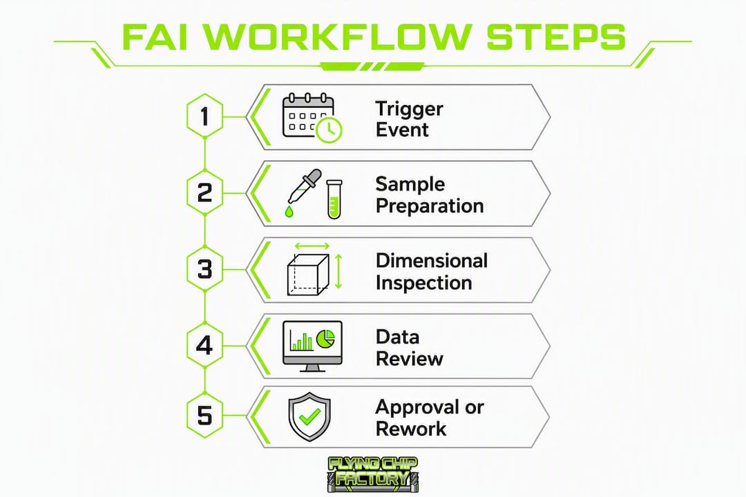
How to run an FAI: the step-by-step workflow
- Balloon the drawing. Number every measurable characteristic sequentially on a copy of the released drawing. Include dimensions, tolerances, GD&T callouts, surface finish symbols, thread notes, and any general notes that specify a measurable requirement.
- Confirm drawing revision. Verify the ballooned drawing matches the current released revision before measuring anything.
- Select the production-representative sample. Pull from the first production lot run under actual conditions — production tooling, production material, production operator, production program revision.
- Measure each characteristic. Work through the balloon list in order. Record nominal, tolerance, measured actual, measurement method, and gage ID for every row.
- Select the right equipment. CMM for complex 3D geometry and GD&T; calipers and micrometers for straightforward linear dimensions; thread gauges for threaded features; profilometer for surface finish; optical comparator or 3D scanner for profile and contour. Match the gage to the tolerance — a 0.001" tolerance feature measured with a caliper that has 0.001" resolution is marginal at best.
- Verify MSA and calibration traceability. Every gage used must have a current calibration record. For critical characteristics, a basic Gage R&R confirms the measurement system is not consuming a significant portion of the tolerance.
- Collect material and special-process evidence. Attach mill certs, heat-treat records, finishing certs, and any Nadcap or customer-approved processor documentation.
- Conduct internal QA review. A second set of eyes on the FAIR before submission catches transcription errors, missing certs, and out-of-tolerance characteristics that need disposition.
- Submit to customer. Transmit the complete FAIR package per the customer's required format (AS9102 forms, PPAP dimensional results sheet, or a generic FAIR template). Note the submission date and track approval status.
- Retain the approved FAIR. File it as the baseline reference for future delta FAIs, audits, and production transfers.
Pro Tip: Prepare the CMM program and fixture setup before the first production run. Running the CMM program on the first sample immediately after machining, while the setup is still live, lets you catch and correct offset errors before the lot progresses.
What happens after the FAI: pass, fail, and re-inspection
On a pass:
- The FAIR is approved and filed as the production baseline
- Production proceeds; the approved FAIR travels with the part number in the quality management system
- Update the control plan if the FAI revealed any measurement or process adjustments
- The approved FAIR becomes the reference document for any future delta FAI
On a fail:
- Stop the affected lot immediately; do not ship nonconforming product
- Identify root cause — setup error, tooling wear, programming issue, material nonconformance, or process deviation
- Disposition nonconforming parts: rework, scrap, or submit a deviation/waiver request to the customer
- Implement corrective action and document it
- Notify the customer per your contract's nonconformance notification requirements
- Run a re-FAI: full re-inspection if the root cause affected multiple characteristics or the process baseline; delta re-FAI if the corrective action was scoped to specific features
The decision point between full and delta re-FAI hinges on the nature of the failure. A worn cutting tool that shifted one diameter is a delta re-FAI candidate. A fixture that was improperly located and affected positional relationships across the part requires a full re-inspection.
Customer notification timing matters. Most aerospace and defense contracts require notification within 24–48 hours of discovering a nonconformance. Check your contract terms before assuming you have time to fix and re-inspect quietly.

Practical tips to speed up FAIs and avoid rework
Pre-FAI readiness checklist:
- Drawing revision confirmed and released
- All gages calibrated with current records on file
- Special-process approvals (heat treat, anodize, plating) scheduled and confirmed before first run
- Material certs in hand and verified against drawing material callout
- Program revision and tool offsets recorded and locked
- Fixture ID documented
Process tips that cut iterations:
- Use digital ballooning software (such as Discus Software's FAI module or similar tools) to number characteristics consistently and generate the dimensional record template automatically
- Prepare the CMM program from the CAD model before the part arrives at inspection
- Use a checklist-based handoff between machining and inspection so nothing falls through the gap between departments
- Communicate with the customer's quality team before the FAI, not after — confirm their required format, any customer-specific forms, and whether source inspection is needed
Pro Tip: Record the production setup parameters in the FAIR itself: tool offsets, fixture ID, program revision number, and cutting parameters. If a re-FAI or production transfer is needed later, that data lets the next operator reproduce the setup without guesswork.
In practice, many shops treat FAI as a flexible family of reports — AS9102 for aerospace, PPAP dimensional results for automotive, or a generic FAIR for other industries — because the core measurement work is identical. Invest in the ballooning and measurement process; the packaging adapts to the customer.
How Flying Chip Factory runs FAIs
At Flying Chip Factory in Athens, Alabama, the FAI workflow is built into every prototype and short-run job from the quoting stage forward. Here is the shop's typical sequence:
- Day 0: Drawing review and ballooning. The machinist and quality function review the drawing together, identify all measurable characteristics, and balloon the print before programming begins.
- Day 1: Setup and first run under production conditions. Tooling, fixturing, and program revision are locked. The first lot runs with production material.
- Day 2: Sample selection, measurement, and FAIR compilation. A production-representative sample is pulled, measured against every balloon, and the FAIR package is assembled with material certs and any process records.
- Day 3: Internal QA review and customer submission. The completed FAIR is reviewed internally, then transmitted to the customer with the part or ahead of shipment.
Pro Tip: Direct access to the machinist during the FAI phase is the single biggest time-saver in short-run work. When a measurement falls close to tolerance, the machinist can immediately evaluate whether an offset adjustment is warranted — no ticket queue, no waiting for a supervisor to relay the question. That loop closes in minutes, not days.
The shop's in-house product development work, including CNC-machined motorcycle parts, means the team runs FAIs on its own designs regularly. That firsthand experience with the full cycle from drawing to approved FAIR informs how Flying Chip Factory supports customers through the same process.
Key Takeaways
A first article inspection is the documented, characteristic-by-characteristic verification that a production-representative part conforms to every drawing requirement, and it must be completed before production ships.
| Point | Details |
|---|---|
| FAI triggers | New part, ECN, process or tooling change, facility transfer, and long production gap all require a full FAI. |
| Core documents | Every FAI needs a ballooned drawing, dimensional record, material certs, and special-process evidence. |
| FAI vs. PPAP | FAI verifies part-level conformance; PPAP is a broader system-level approval that includes FAI-style dimensional results plus PFMEA, control plan, and capability data. |
| AS9102 context | Aerospace FAIs use Forms 1–3; automotive uses PPAP dimensional results; other industries use a generic FAIR — the ballooning and measurement work is the same across all three. |
| Flying Chip Factory | Flying Chip Factory handles ballooning, CMM measurement, FAIR compilation, and customer submission for prototype and short-run CNC parts from its Athens, Alabama shop. |
Why rigorous FAIs matter more in short-run work
The conventional wisdom treats FAI as a bureaucratic hurdle — something you do because the contract requires it. That framing gets it backwards, especially in prototype and short-run machining.
In high-volume production, a process capability study gives you statistical confidence that the process is centered and stable. In short-run work, you rarely have enough parts for a meaningful Cpk. The FAI is your substitute for that statistical confidence. It is the one structured moment where you verify that the process, as it actually ran, produced a conforming part. Skip it or rush it, and you are shipping on faith.
The documentation discipline matters just as much as the measurement. A FAIR that captures tool offsets, fixture IDs, and program revision numbers is a reproducibility record. When a customer reorders six months later, or when a part needs rework after delivery, that record tells you exactly how the part was made. Without it, you are starting from scratch.
The shops that treat FAI as a value-added step rather than a compliance checkbox tend to catch problems earlier, iterate faster, and build customer relationships that survive the inevitable first nonconformance. Because when something goes wrong, a complete FAIR is the fastest path to root cause — and root cause is the fastest path to a fix.
Flying Chip Factory handles your FAI from drawing to approval
Short-run CNC work demands FAI discipline that most job shops treat as optional. Flying Chip Factory brings a different standard: every prototype and production run goes through a structured FAI process, from ballooned drawing to compiled FAIR, before parts ship.

The shop handles the full sequence: CNC machining under production conditions, CMM measurement of all drawing characteristics, FAIR compilation with material certs and process records, internal QA review, and customer submission in your required format — AS9102, PPAP dimensional results, or a generic FAIR. Direct machinist access means measurement questions get answered in real time, not after a two-day email chain.
If you have a prototype or short-run part that needs a compliant FAI alongside the machined parts, submit your drawing at Flying Chip Factory and get a quote that includes the inspection package.
Useful resources and standards
- AS9102 Rev D — the authoritative aerospace FAI standard; defines Forms 1–3 and requirements for U.S. aerospace and defense supply chains
- AIAG PPAP Manual (4th Edition) — the definitive reference for automotive PPAP submissions, including PPAP levels explained and submission requirements for the U.S. automotive supply chain
- ASME Y14.5-2018 — the U.S. standard for GD&T; required reading for anyone ballooning drawings or interpreting tolerance callouts during an FAI
- First article inspection overview (Wikipedia) — a useful starting point for general FAI concepts and sampling guidance
Authority by industry: AS9102 governs U.S. aerospace and defense; the AIAG PPAP manual governs U.S. automotive; ASME Y14.5 applies across all industries for GD&T interpretation. For general manufacturing without a customer-specified standard, a generic FAIR built around a ballooned drawing and dimensional record satisfies most audit and traceability requirements.