
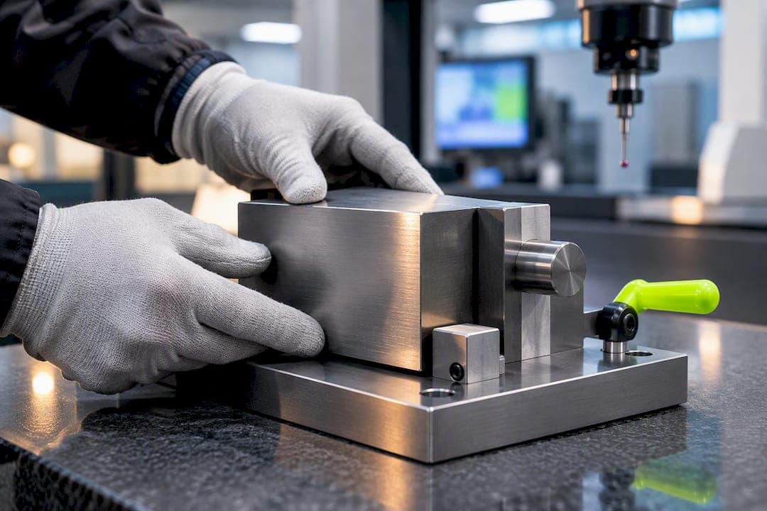
A GD&T datum is a theoretical reference plane, axis, or point that serves as the origin for geometric tolerances, not a physical surface you can touch. Every datum gets established from a real feature on the part, but the datum itself stays perfect and imaginary. That distinction drives how parts get inspected, how fixtures get built, and whether a stack of tolerances actually lets two parts assemble.
TL;DR:
- Proper datum selection should reflect how the part actually contacts its mating components, not just which surface is easiest to fixture or measure.
- A datum is derived from a real feature through simulation, meaning a perfect reference point, axis, or plane is never measured directly but established via a fixture or CMM.
- The correct order of datums based on the 3-2-1 rule is essential, as changing it alters the measurement reference and can lead to inconsistent inspection results.
- Common datum types include planar surfaces, bore axes, and center planes, chosen according to how the part is assembled and functionally constrained.
- Validating the datum scheme on a prototype or first-off part before full production saves cost, ensuring measurement and assembly accuracy align with design intent.
GD&T Datums: The Formal Definition and Why They Matter
A datum, under ASME Y14.5's own conventions, is a theoretically exact point, axis, line, or plane. It has zero form error, zero waviness, and zero of the imperfections you'd find on any machined surface. It cannot be measured directly for that reason. What gets measured is a real feature that stands in for the datum, an idea worth sitting with before anything else about GD&T makes sense.
This matters because a datum is what turns a drawing callout into a repeatable measurement setup. When a tolerance zone says "positioned within 0.1 mm relative to A, B, C," the inspector needs to know exactly where A, B, and C sit in space before that number means anything. Without an established reference frame, "positioned within 0.1 mm" is meaningless.
Almost every GD&T symbol relies on a datum to define location or orientation. The exceptions are the pure form controls (flatness, straightness, circularity, cylindricity), which evaluate a feature relative to itself. Position, perpendicularity, angularity, and runout all reference back to a datum reference frame.
- Pure form tolerances: no datum required
- Orientation and location tolerances: datum required
- Runout: datum axis required
- Profile controls: usually datum referenced
Pro tip: If a feature control frame has no datum reference letters in the third compartment, check whether it's a form tolerance. If it isn't, something is missing from the drawing.
Datum Features Are Physical. Datums Are Not.
A datum feature is the real, physical surface, bore, or flat noted on the drawing with a datum feature symbol. Common examples include a machined base, a bore that locates a shaft, or two opposing faces on a bracket. The datum feature is what a machinist can touch and a CMM probe can actually contact.
The datum itself gets extracted from that feature through simulation. GD&T Basics describes this clearly: because real surfaces always carry some form error, you need a simulator, a device treated as perfect for inspection purposes, to stand in for the theoretical datum. A surface plate simulates a planar datum. A gauge pin or mandrel simulates an axial datum from a bore. A CMM's best-fit plane algorithm does the same job digitally.
This distinction has real teeth in fixture design. A fixture built against the wrong idea of "datum" (treating the imperfect feature as the datum itself instead of simulating it properly) will pass parts that don't actually meet spec, or reject parts that do.
- Datum feature: the actual surface or bore called out on the drawing
- Simulator: the surface plate, pin, mandrel, or CMM construction that stands in for the theoretical datum
- Datum: the perfect plane, axis, or point derived from that simulation
Building a Datum Reference Frame: The 3-2-1 Rule Explained
A datum reference frame, or DRF, locks a part's position in space so every dimension on the drawing can be measured against a known origin. It gets built from up to three datums, ordered by precedence: primary, secondary, and tertiary. Order isn't cosmetic. It changes which surface controls which degrees of freedom, and changing that order can change your inspection results even on an identical part.
The 3-2-1 rule explains how this works mechanically. A rigid part has six degrees of freedom: translation along three axes and rotation about three axes.
- The primary datum contacts the part at three points, constraining three degrees of freedom (one rotation pair plus translation along that axis).
- The secondary datum contacts at two points, constraining two more degrees of freedom.
- The tertiary datum contacts at one point, constraining the final degree of freedom.
Picture a rectangular bracket. Datum A is the bottom face, sitting flat on a surface plate; that's your three-point contact. Datum B is one edge, pushed against a fence, eliminating rotation and one translation. Datum C is an end face, stopped against a single pin, killing the last degree of freedom. All six are now locked, and the part has a defined position relative to the DRF.
Swap the order, say, using the edge as primary instead of the bottom face, and the part sits differently in the simulated setup. Measurements taken from that new orientation won't match the first. That's why datum precedence has to reflect how the part actually functions in its assembly, not just which surface is biggest or easiest to fixture.

Types of Datums You'll See on Real Drawings
Planar datums come from flat surfaces and almost always work best as the primary reference when the part has one dominant mounting face. A machined base, a mounting flange, a gasket face, these are natural planar datum candidates because they typically match how the part sits in its actual assembly.
Axial datums come from a bore or shaft's derived centerline. They usually work as secondary or tertiary references, particularly on parts that locate around a pin, bolt, or bearing bore. A gauge pin inserted into the bore establishes the axis for inspection purposes.
Center or median plane datums come from a feature of size with two opposing surfaces, think a slot, a tab, or a symmetric boss. Instead of referencing one face, the datum sits at the midpoint between both surfaces, which matters when a part needs to be symmetric about a centerline rather than located from one edge.
Datum targets solve a different problem: irregular castings, sheet metal, or flexible parts where a full surface contact isn't practical or repeatable. Rather than referencing an entire plane, you specify individual point, line, or area targets. Multiple targets together define a plane the same way three legs define a stable table, and Xometry's overview of datum types covers this well for parts that don't offer a clean, continuous reference surface.
- Planar: flat mounting faces, gasket surfaces, base plates
- Axial: bores, shafts, pin locations
- Center plane: slots, symmetric bosses, tabs
- Targets: castings, weldments, thin or flexible parts
Choosing the Right Datums: What Actually Works
Pick functional mating surfaces, not whatever face happens to be flattest or easiest to clamp. The datum scheme should mirror how the part actually contacts its mating component in the final assembly. Guidance from GD&T Basics on datum reference frames makes the point directly: a part can pass every dimension on the print and still fail to assemble if the datums don't reflect real assembly contact.
Run candidate datum features through a short mental checklist before locking them into the drawing.
- Is the surface large and stable enough to seat repeatably, or will small burrs or draft angles cause rocking?
- Does the feature actually contact the mating part, or is it just convenient to fixture?
- Can a machinist or inspector realistically access it with a gauge pin, mandrel, or CMM probe?
The most common mistake is choosing a cosmetic or "nice flat surface" as a datum simply because it's easy to reference, while ignoring where the part actually locates in its assembly. A close second is treating datum order as arbitrary rather than functional. A third, subtler mistake is over-constraining a part with more datum features than the six degrees of freedom actually require, which creates conflicting reference points and inspection headaches nobody asked for.
Pro tip: Before finalizing a datum scheme, sketch how the part sits in its mating assembly and mark the actual contact points. If your proposed primary datum isn't one of those contact points, reconsider it.
From Drawing to Fixture: How Shops Actually Simulate Datums
On the shop floor, a datum only becomes useful once it's simulated with real equipment. A granite surface plate stands in for a planar primary datum. Gauge pins and mandrels simulate axial datums pulled from bores, and a CMM's best-fit plane or cylinder construction does the same job digitally when hard fixturing isn't practical, a point echoed in metrology guidance on simulated datums.
A few quick checks catch problems before they become scrapped parts:
- Confirm three-point contact on the primary datum, not two points and a rock
- Size gauge pins to the bore's actual tolerance, not a nominal guess
- Verify the CMM's programmed DRF matches the drawing's datum order, not just its datum letters
- Watch for burrs or witness marks at simulator contact points, they throw off repeatability fast
A shop builds fixtures and short-run prototype parts around this exact logic, treating the datum scheme on the print as the starting point for how a part gets held and measured, not an afterthought.
Why Functional Datums Beat Convenient Ones
The single biggest lesson buried in most GD&T instruction is this: a datum scheme should describe how the part works, not how it sits easiest on a bench. Engineers who treat datum selection as a formality, picking whatever face is biggest or flattest, end up with parts that pass every inspection and still rattle, bind, or misalign once bolted to something else.
The fix isn't more tolerance, it's better reference logic. Before a print goes final, walk the datum scheme against an actual fixture or CMM plan and ask whether the simulated setup matches real assembly contact. If it doesn't, no amount of tightened tolerance will save the fit. For anyone building a prototype where that mismatch would be expensive to discover late, a quick conversation with a machinist before cutting metal tends to be worth more than another round of drawing revisions.
— Drake
Get Your Datum-Critical Parts Validated Before You Scale Up
Catching a bad datum scheme on paper is cheap. Catching it after a production run ships is not. A shop runs prototype machining, short-run production, and fixture and gauge fabrication out of a single location, with direct access to the machinist handling your job, no sales layer between your question and the person cutting the part.

That direct line matters most when a datum scheme looks fine on the drawing but needs a second set of eyes before it's committed to a full run. Send over a print with a questionable datum reference frame, and get a fixture or first-off part built to test it against a real CMM setup rather than an assumption. The shop also machines its own line of parts, including the E2 Kickstand for KTM SX-E 2, GASGAS MC-E 2, and Husqvarna EE 2 electric mini dirt bikes at $100 to $105 one-off, built with the same fixture-first approach used on customer jobs. If your next part depends on getting a datum scheme right the first time, start a quote request and talk directly with the machinist who'll build it.
Sources
For deeper study beyond this explainer, go straight to the ASME Y14.5 standard for the governing conventions, and pair it with practical breakdowns on datum-controlled degrees of freedom and calibration management for QA teams running datum-based inspection programs.
- ASME Y14.5 standard excerpts (pdf)
- Datum Feature | GD&T Basics
- Datum in GD&T: Definition, Features, and Types in Engineering Drawings | Xometry
FAQ
What Is the 3-2-1 Rule in GD&T?
The 3-2-1 rule describes how a part's six degrees of freedom get constrained by three ordered datums. The primary datum contacts three points, the secondary contacts two points, and the tertiary contacts one point, together locking the part fully in space for measurement.
What Are the Three Types of Datum?
Datums are typically categorized as planar, axial, and center or median plane, based on the feature they're derived from. Planar datums come from flat surfaces, axial datums come from bores or shafts, and center plane datums come from opposing surfaces of a feature of size like a slot or tab.
Which GD&T Symbols Need a Datum?
Nearly every GD&T control except pure form tolerances (flatness, straightness, circularity, and cylindricity) requires a datum reference. Position, orientation, and runout controls all need at least one datum to define where the tolerance zone sits in space.
Can You Explain GD&T Datums Simply?
A datum is a perfect, invisible reference plane, axis, or point that a real surface stands in for during inspection. Think of it as the theoretical zero point a part gets measured against, established by pressing a real feature against a simulator like a surface plate or gauge pin.
Does Flying Chip Factory Build Fixtures for Datum Validation?
Yes. Flying Chip Factory offers prototype machining, short-run production, and fixture and gauge fabrication, with direct machinist access for quick iteration on datum-critical designs. Pricing for custom fixture and prototype work is available on request through the shop's service page.