
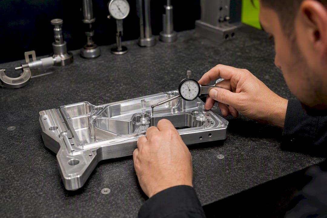
BLUF: flatness controls the form of a single surface and needs no datum; parallelism controls orientation to a datum and, in doing so, also limits how flat that surface can be. That's the entire distinction in one sentence, but it's the one most drawings get wrong.
Here's what that means when you're specifying or inspecting a part:
- Use flatness when the surface only needs to be true to itself. Gasket faces, optical windows, and vacuum-chuck surfaces care about local waviness, not what the surface points at.
- Use parallelism when the surface's orientation to another feature matters. Rail ways, mounting platens, and bearing bores need to sit square to a reference, not just be smooth.
- Inspection follows the same split: flatness gets measured against itself on a surface plate or CMM with no datum setup. Parallelism gets measured relative to a datum, which means fixturing, alignment, and a second reference surface enter the picture before you take a single reading.
Key Takeaways
Flatness controls a surface's own form with no datum, while parallelism controls orientation to a datum and inherently limits flatness within its zone.
| Point | Details |
|---|---|
| Datum is the dividing line | Flatness needs no datum reference; parallelism always requires one in the feature control frame. |
| Parallelism caps flatness | A parallelism zone limits local waviness unless a tighter flatness tolerance is called out separately. |
| Match control to function | Use flatness for sealing or optical faces, parallelism for mating or mounting surfaces. |
| Tight tolerances raise cost | Specs near 0.001 inches often demand stress-relieved stock and added CMM verification time. |
| Document inspection method | Stating the evaluation method on the print avoids RFIs and shop misinterpretation. |
Flatness vs Parallelism Definitions in GD&T
Flatness is a form tolerance. The ASME Y14.5 and ISO GD&T systems define it as the condition where every point on a surface falls between two parallel planes, separated by the tolerance value, with no reference to anything outside that surface. The symbol is a flattened parallelogram, and the feature control frame carries no datum reference at all, ever. If you see a datum letter tucked into a flatness callout, something's wrong with the drawing.
Parallelism is an orientation tolerance. It also uses two parallel planes as its zone, but those planes are locked parallel to a specified datum plane or axis. The symbol is two forward slashes (//), and the feature control frame always includes a datum reference. CNCCookbook's breakdown of parallelism makes the mechanical difference clear: parallelism controls tilt relative to a datum, while flatness only judges a surface against itself.
Statistic Callout: ISO 12781-1 recognizes several distinct flatness metrics, including least-squares deviation, minimum-zone deviation, and RMS flatness deviation, according to Wikipedia's summary of flatness measurement standards). Which metric your CMM software defaults to changes the reported number, sometimes by a meaningful margin on the same physical part.
A typical flatness callout looks like this in a feature control frame:
- ⏥ | 0.002 |
A typical parallelism callout adds the datum:
- // | 0.001 | A
Notice the parallelism callout is tighter here. That's common. Parallelism tolerances often need to be smaller than a flatness tolerance would be on the same surface, because they're doing two jobs: holding the surface true to itself and holding it square to a datum.
Why the Tolerance Zone Looks the Same but Behaves Differently
Both controls define their zone as two parallel planes separated by the tolerance value. Geometrically, if you handed an inspector a shaded model of a flatness zone and a parallelism zone with the same numeric tolerance, they'd look identical. The difference is orientation: a flatness zone floats freely, oriented however best fits the actual surface. A parallelism zone is locked parallel to the datum, no matter how the surface actually sits.
That distinction drives two different evaluation methods:
- Minimum-zone evaluation finds the smallest possible gap between two parallel planes that fully contain the surface. This is the strict, ASME/ISO-conformant method and the one most CMM software defaults to for pass/fail decisions.
- Least-squares evaluation fits a best-fit reference plane through the data using regression, then reports deviation from that plane. It's faster to compute and useful for process monitoring, but it can under-report the true minimum-zone value.
Here's the part that surprises a lot of engineers: specifying parallelism does not guarantee flatness better than the parallelism tolerance itself. A surface can sit anywhere inside that datum-parallel zone, including with local waviness that eats most of the available tolerance. If the surface needs to be both parallel to a datum and locally smoother than the parallelism zone allows, you need a separate, tighter flatness callout inside it.
Pro Tip: When a print calls out parallelism only, don't assume the surface will be dead flat. Check whether the application needs a supplemental flatness tolerance tighter than the parallelism value, and specify minimum-zone evaluation explicitly if the part is going into a high-stakes mating application.
How to Measure Flatness vs Parallelism on the Shop Floor and CMM
Measurement approach depends on what you're checking and how much precision the application demands.
- Surface plate and dial indicator (flatness). Set the part on a granite surface plate, sweep a dial indicator across the surface in a grid pattern, and record high and low readings. The spread between the highest and lowest point is your flatness deviation. No datum setup required, since you're only comparing the surface to itself.
- Optical flats and interferometry (flatness). For optical components or lapped surfaces, an optical flat and monochromatic light source reveal interference fringes. Counting fringes gives sub-micron flatness data, far beyond what a dial indicator can resolve.
- CMM point-cloud evaluation (flatness or parallelism). A CMM probes a dense grid of points across the surface, then software fits either a least-squares plane or calculates the minimum-zone solution. For parallelism, the software also establishes the datum plane first, aligns the part coordinate system to it, then evaluates the target surface relative to that alignment.
- Fixture-referenced parallelism checks. In the shop, this often means clamping or resting the datum surface on the plate, then indicating the toleranced surface directly. No separate alignment step needed if the fixture itself constrains the datum correctly.
CMM software like PC-DMIS handles the heavy lifting on parallelism by deriving the toleranced feature and optimizing the tolerance zone relative to the established datum, according to Hexagon's PC-DMIS documentation on parallelism evaluation. The catch: measured value depends heavily on point density. A sparse point cloud can report a smaller, more favorable deviation than the part actually has, simply because it missed the true high and low points.
CMM wins on accuracy, repeatability, and the ability to evaluate MMC or LMC modifiers against actual mating size. A surface plate and dial indicator win on speed and cost for a quick in-process check, especially in a prototype shop where a part might get inspected three times before it leaves the building. Neither replaces the other; they answer different questions at different points in the build.
When Should You Specify Flatness, Parallelism, or Both?
The decision rule is simpler than most drawings suggest: does this surface mate with or reference another feature? If yes, you need an orientation control like parallelism. If no, flatness alone does the job.
A few concrete scenarios make this stick:
- A gasket sealing face on a housing only needs flatness. Nothing else on the part cares which way that face is tilted, only that it seals evenly.
- A mounting platen that has to sit square against a datum face on an assembly needs parallelism, since the whole point of the surface is its relationship to something else.
- A rail-mounting surface on a linear guide system needs parallelism to the mating rail's datum, or the carriage binds under load.
- A cosmetic pocket with no mating function usually needs no form or orientation control beyond the general profile tolerance already on the drawing.
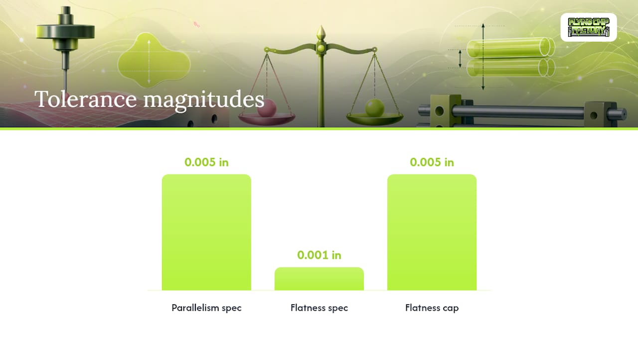
Sometimes you need both, and this is where a lot of drawings get sloppy. If a mounting surface needs to be parallel to a datum within 0.005 inches but also needs local flatness tighter than that, say 0.001 inches, for a precision optic to seat correctly, you specify parallelism to the datum and a separate, tighter flatness callout on the same surface. Skip the flatness callout and the surface could still pass parallelism inspection while having enough local waviness to throw off the optic.
A parallelism tolerance zone is two planes parallel to the datum, and the surface has to lie inside them. That alone caps flatness at the parallelism value, according to MakerStage's GD&T comparison guide, unless you separately call out something tighter.
Document the datum reference frame clearly and specify the inspection method on the drawing or in a note when it's not obvious. A missing datum label is one of the most common sources of an RFI (request for information) on a prototype job, and it stalls a quote or a production run for no good reason.
What Tight Flatness and Parallelism Tolerances Cost You in the Shop
Tolerance choice drives process choice, and process choice drives lead time and price. This isn't abstract. It shows up in every quote.
Loosen a flatness or parallelism call to 0.005 inches on a mid-size aluminum part, and a single finish pass on a well-tuned mill usually gets you there. Push that same tolerance to 0.001 inches or tighter, and the process changes entirely: stress-relieved stock to avoid warp after machining, a dedicated finish pass with lighter cuts, precision fixturing to control clamping distortion, and often a second operation with a fixture flip and reindication to hit both sides. According to MakerStage's guidance on GD&T cost implications, tolerances in the 0.0005 to 0.001 inch range routinely require special stock preparation and added inspection time, and that's before you factor in CMM programming time to verify it.
A few patterns worth knowing before you tighten anything on a print:
- Redundant callouts cost money with zero functional payoff. A tight flatness spec on a surface that already has an equally tight parallelism callout adds inspection time without tightening anything real.
- Material choice matters more than people expect. A part cut from stock with high residual stress can warp after machining removes material asymmetrically, blowing a flatness spec that measured fine right off the mill. Our guide on T6 vs T6511 aluminum tempers covers how temper selection affects this on larger, thinner parts.
- Surface finish and coating steps can shift flatness after the fact. Anodizing, for instance, adds a measurable layer that can change dimensions at tight tolerances, something worth reviewing in our hardcoat anodize thickness guide.
Pro Tip: Write drawing notes that state the datum feature and the required inspection method explicitly, like "verify parallelism per CMM with minimum-zone evaluation." That single line prevents most of the back-and-forth RFIs that stall a quote.
How Flying Chip Factory Handles Flatness and Parallelism Callouts
Every print that comes through Flying Chip Factory gets a read for datum structure before it gets a quote. If a part calls out parallelism without a clear datum reference frame, or asks for a flatness tolerance tighter than the parallelism zone it sits inside without stating why, that gets flagged before we cut anything. Direct access to the machinist running the job means those questions get answered in a phone call or a message, not a multi-day RFI cycle through a sales layer.
For short-run and prototype work, this catches real problems early:
- We push back on redundant callouts, like a flatness spec matching or exceeding a parallelism value on the same surface, since it adds CMM time without adding function.
- We estimate inspection time based on whether a part needs surface-plate checks or full CMM verification, since that changes turnaround more than the machining itself does.
- For parts needing repeat inspection across a short run, we build a fixture once and reindicate rather than re-referencing datums from scratch every part, which keeps repeatability tight without inflating cost per unit.
Our slot machining guide and go/no-go gauge guide walk through related fixturing and inspection templates worth reviewing before you finalize a print.
| Point | Details |
|---|---|
| Datum check first | Flying Chip Factory reviews datum structure before quoting to catch missing references early. |
| Redundancy flagged | Callouts that duplicate an existing tolerance get flagged to avoid unnecessary inspection cost. |
| Fixture reuse | Short runs use one fixture setup across parts to hold repeatability without added per-part cost. |
An Editorial Take on Getting Flatness and Parallelism Right
Most GD&T explainers treat flatness and parallelism as a vocabulary problem. Learn the symbols, memorize the definitions, move on. That framing undersells the actual risk, which is functional, not linguistic. The costly mistake isn't confusing the symbols; it's assuming a parallelism callout does a flatness callout's job.
The evidence here points to a sharper priority than most guides offer: check whether the surface has a mating function before you touch a symbol. That single question, asked before the drawing leaves an engineer's desk, prevents more downstream cost than any amount of memorized zone geometry. Conventional advice spends too much time on "here's what the symbols mean" and not enough on "here's what happens when you specify parallelism alone and the surface still fails to seal."
Machinists live with the consequences of vague prints daily. A tighter tolerance than the application needs burns budget on unnecessary finish passes and CMM time. A missing datum reference burns days on RFIs. The reader's real job isn't learning definitions; it's asking, before anything gets cut, exactly what the surface has to do once it leaves the shop.
Sources
- GDT: Parallelism symbol, tolerance, measurement — CNCCookbook
- Flatness vs Parallelism vs Perpendicularity in GD&T (2026) — MakerStage