

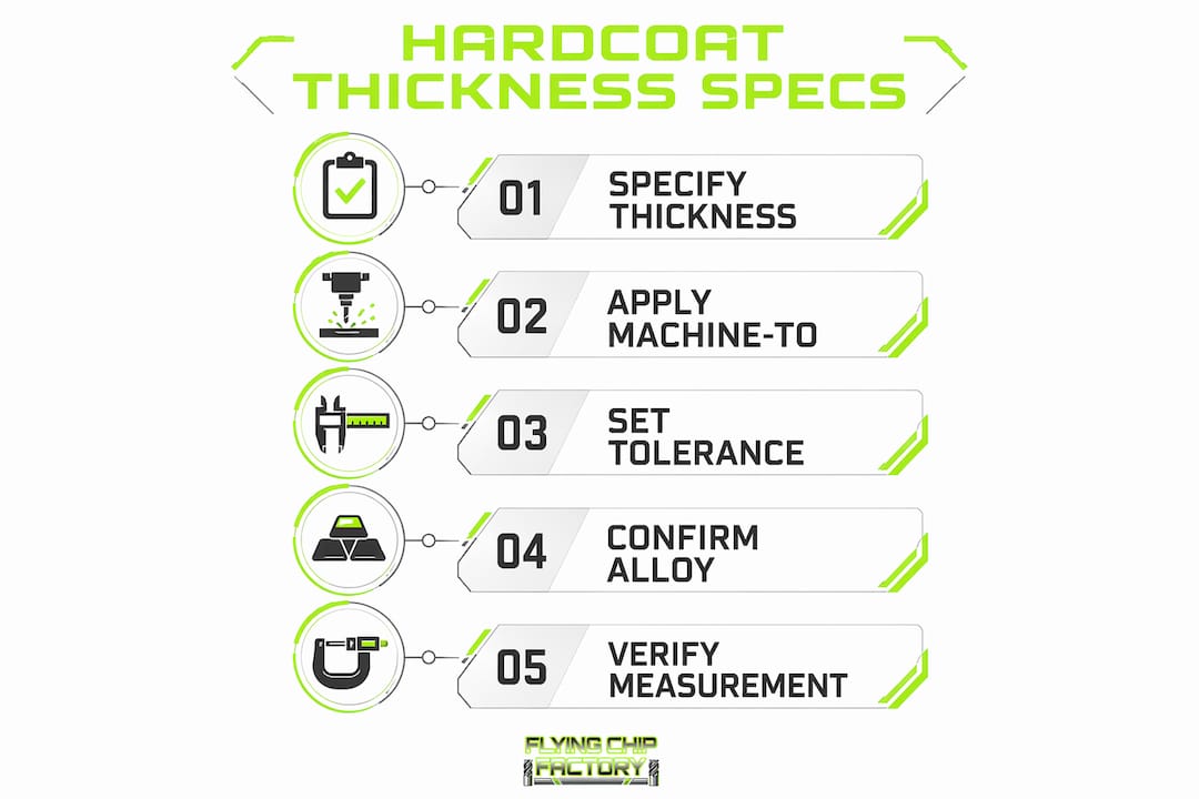
Specify Type III hardcoat anodize at 0.002" ± 0.0004" as your drawing default unless a specific wear or tolerance requirement demands otherwise. That's the NASA PRC‑5006 default, it's what most shops quote, and it's the number MIL‑A‑8625 Type III practitioners recognize immediately. Half of the coating thickness typically builds up on the surface; the other half penetrates the base metal. So a shaft machined to a target dimension will increase approximately half the coating thickness per surface after coating.
When to deviate from 0.002":
- Thicker (up to ~0.003"): High-wear surfaces, sliding contact, or dielectric requirements justify going up. Stay under 0.0035" or you risk brittleness.
- Thinner (0.0005"–0.001"): Tight-tolerance bores, thin walls, or features where dimensional change must be minimized.
- Sealed vs. unsealed: Seal only when corrosion resistance is the primary requirement. Sealing reduces wear resistance.
Pro Tip: Put the 50/50 rule on your drawing notes. "Machine to [dimension] to allow for 0.001" hardcoat build-up per surface" saves a phone call every time.
Table of Contents
- What hardcoat anodize thickness ranges are practical for CNC parts?
- How does coating thickness affect wear, corrosion, and fatigue?
- Why coating thickness varies across complex geometry
- How to write engineering drawing callouts for hardcoat anodize
- How shops measure hardcoat thickness in practice
- Process constraints that affect schedule and manufacturability
- What to hand your machinist before machining for hardcoat anodize
- Key Takeaways
- The mistake that causes most hardcoat rejects
- Flying Chip Factory machines parts right for hardcoat anodize
- Useful sources for your drawings and purchase orders
What hardcoat anodize thickness ranges are practical for CNC parts?
Type III hardcoat runs from roughly 0.0005" to 0.0035" in normal shop practice, with 0.002" as the standard nominal. Beyond 0.0035", coatings tend to become brittle, can chip, and often develop a milky appearance. That's not a hard wall, but it's where the engineering trade-offs stop making sense for most CNC parts.
| Thickness (inches) | Thickness (microns) | Typical use case |
|---|---|---|
| 0.0005" | 13 | Minimal dimensional change, light wear |
| 0.001" | 25 | General purpose, tight-tolerance features |
| 0.002" | 51 | Default shop nominal, balanced wear/corrosion |
| 0.003" | 76 | Wear surfaces, sliding contact |
| 0.0035" | 89 | Near practical maximum for most alloys |
Common shop limits to know:
- Minimum reliable thickness: a very thin coating
- Default nominal is commonly quoted as 0.002"
- Practical maximum thickness varies by alloy and processing
- Tolerance guidance is given by NASA PRC‑5006 and may be tighter under rigorous process control
Abrasion resistance in Type III hardcoat does not increase linearly with thickness. Above roughly 3 mils (0.003"), abrasion resistance can actually decrease as the coating becomes denser and more brittle.
How does coating thickness affect wear, corrosion, and fatigue?
Thicker hardcoat increases dielectric strength and initial abrasion resistance up to about 0.003", then the relationship reverses. Fatigue is the less-discussed consequence: anodic coatings introduce surface stress, and thicker coatings amplify that effect. As a rule, the thicker the coating, the greater the fatigue reduction in the base alloy.
Key property trade-offs by thickness:
- Wear resistance: Peaks around 0.002"–0.003"; drops above 0.003" due to brittleness
- Corrosion resistance: Improves with thickness; sealing adds another layer of protection
- Dielectric strength: Scales with thickness (hardcoat is a common electrical insulator in motor and actuator applications)
- Fatigue strength: Decreases as thickness increases, especially in high-cycle applications
- Dimensional change: Directly proportional; every 0.001" of coating adds 0.0005" per surface
The sealing trade-off is real and often misunderstood. Sealing closes the pores, which improves corrosion resistance but reduces the surface hardness that makes hardcoat useful for wear applications.
Pro Tip: Default to unsealed when the part sees abrasion or sliding contact. Specify sealed only when the drawing notes a corrosion requirement. Never leave it unspecified — shops will make their own call.
Hardcoat anodize delivers surface hardness comparable to Rockwell C 70, making it one of the hardest finishes achievable on aluminum without thermal spray.
Why coating thickness varies across complex geometry
Current density drives coating growth, and current density is not uniform across a complex part. Inside a tube, a deep hole, or a narrow slot, the electrolyte has less access and the current thins out. NASA PRC‑5006 explicitly flags that inner surfaces of tubing and deep holes typically plate thinner than outside surfaces.
Design implications by feature type:
- Outside surfaces: Coat at or above nominal; easiest to control
- Inside diameters / bores: Expect thinner coating; specify minimum acceptable thickness here
- Deep holes (L/D > 4): Coating may be negligible at the bottom; consider masking if coating is not needed
- Sharp edges and corners: Coating builds thicker at edges; radius corners where possible (0.010" min)
- Thin walls: Risk of warping from thermal stress during processing
Alloy choice also sets a ceiling. High-silicon alloys (360, 380, 383 die castings) are difficult or impossible to hardcoat above 2 mils. Heat-treatable alloys should be in their final temper (T4, T6) before anodizing. 6061-T6 is the workhorse: it forms excellent hardcoat up to about 0.0025"–0.003". 7075 runs blue-gray and has its own thickness limits.
Alloy family and practical coating thickness limits vary: 6061-T6 typically allows a moderate maximum thickness with good dimensional stability; 6063 has a slightly lower limit; 7075-T6 can have higher limits but should be confirmed with the finisher; 2024-T4 often requires approval for coating thickness; high-silicon die cast alloys frequently have coating restrictions or are discouraged.
Pro Tip: When a part has both a deep bore and an outside wear surface, consider specifying the outside surface thickness and calling the bore "mask or accept as-coated." Trying to hit the same tolerance on both surfaces in one bath is asking for rework.
How to write engineering drawing callouts for hardcoat anodize
Ambiguous drawing notes are the single biggest source of anodizing rework. Industry guidance is direct: specify nominal thickness, tolerance, measurement method, sampling locations, alloy, sealing requirement, and masking areas on the drawing. Every item left off becomes a phone call or a rejected part.
Three callout examples:
-
General note (default):
FINISH: TYPE III HARDCOAT PER MIL-A-8625, 0.002" ± 0.0004" THICK. ALLOY: 6061-T6. UNSEALED. MEASURE PER ASTM B244. -
Local wear surface callout:
SURFACE A: TYPE III HARDCOAT 0.003" ± 0.0004". MACHINE TO [DIM] BEFORE COATING. UNSEALED. -
Exclusion/mask callout:
THREADS AT [FEATURE]: MASK. DO NOT COAT. CONVERSION COAT IF REQUIRED FOR CORROSION PROTECTION.
Specification checklist for every hardcoat drawing:
- Alloy and temper (e.g., 6061-T6)
- Nominal thickness and tolerance
- Machine-to dimensions (pre-coat) for all critical features
- Masking areas (threads, bearing surfaces, ground surfaces)
- Sealing requirement (sealed or unsealed)
- Measurement method and sampling locations
- Reference standard (MIL-A-8625 Type III, NASA PRC‑5006, ASTM B244)
For V-threads, the build-up × 4 rule estimates pitch-diameter change: multiply build-up per surface by four. A 0.002" coating with 0.001" build-up per surface changes the pitch diameter by 0.004". Machine accordingly and call out masking explicitly.
Pro Tip: Add a drawing note: "Confirm machine-to dimensions with finisher before machining." A five-minute conversation before you cut metal beats a scrapped part.
How shops measure hardcoat thickness in practice
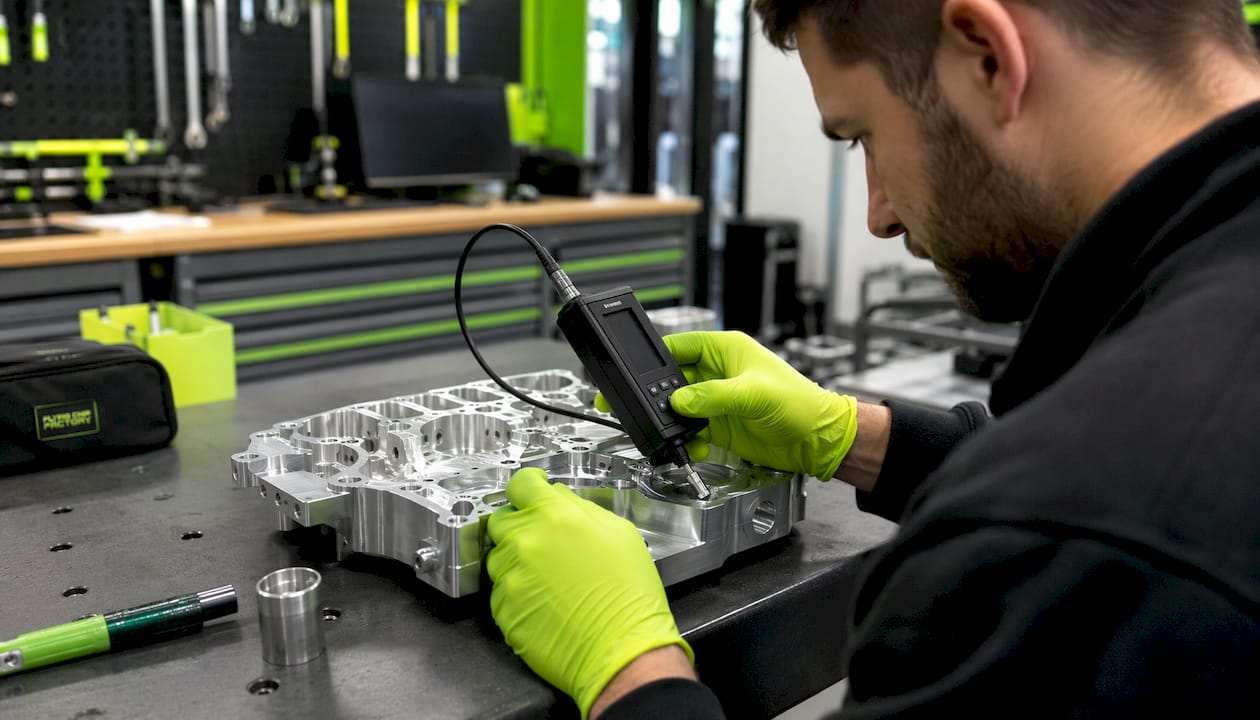
Eddy-current gaging is the standard nondestructive method. Instruments like the DeFelsko PosiTector 6000 NAS probe measure anodizing on aluminum quickly and accurately under 100 µm (4 mils), which covers virtually all hardcoat applications. The method is fast, portable, and leaves the part intact.
Cross-section metallography is destructive but definitive. When a thickness dispute arises or a first-article inspection requires absolute certainty, a perpendicular cross-section under a calibrated microscope resolves it. Specify this method on drawings when the application is safety-critical.
QA guidance for production:
- Specify measurement locations on the drawing (not just "check thickness")
- Require per-part measurement for critical features; panel specimens are acceptable for process control on production runs
- Reference ASTM B244 as the test method for eddy-current measurement
- Define accept/reject criteria: nominal ± tolerance, with no individual reading below minimum
- For rework: stripping and re-anodizing is possible but removes base metal; plan for it in your tolerance stack
When a thickness reading fails, the correct response is to strip and re-anodize — not to accept the part and adjust the drawing. Coating thickness is a functional dimension, not a cosmetic one.
Process constraints that affect schedule and manufacturability
Masking, fixturing, and feature geometry all drive lead time. A part with three masked areas, a tight tolerance, and a complex bore takes longer to process than a simple block. Plan for it.
Common process constraints:
- Minimum feature size for reliable coating: sharp internal corners under 0.005" radius are difficult to coat uniformly
- Threads must be masked or reamed after coating; specify which on the drawing
- Ground surfaces and bearing fits need masking or post-coat grinding allowance
- Fixturing leaves contact marks; specify acceptable contact locations on the drawing
- Thick coatings (above 0.002") require longer bath times and tighter process control, adding lead time
Process review checklist for design:
- Confirm alloy and temper are specified on the drawing
- Identify all features requiring masking
- Calculate machine-to dimensions for all critical surfaces
- Specify sealing requirement
- Define measurement locations and acceptance criteria
- Confirm lead time with finisher before committing to a schedule
Pro Tip: Include finish process notes in the purchase order, not just the drawing. "Confirm masking of M6 threads and provide process control panel results" in the PO prevents surprises at receiving inspection.
What to hand your machinist before machining for hardcoat anodize
Getting the machinist and finisher aligned before the first chip flies is where most rework gets prevented. Specifying alloy and coating thickness early is the single most effective way to avoid delays.
Deliverables package for your CNC partner:
- Alloy and temper (written on the drawing, not just in an email)
- Final post-coat dimensions for all critical features
- Machine-to dimensions (pre-coat) calculated from the 50/50 rule
- Masking drawing or marked-up PDF showing excluded areas
- Desired thickness, tolerance, and sealing requirement
- Inspection point locations and acceptance criteria
Key questions to ask your finisher before machining:
- Can you hold ±0.0004" on this alloy at 0.002" nominal?
- Do you need process control panels, and what alloy/size?
- What are your recommended machine-to allowances for this geometry?
- Can you mask the threads, or should I plan to re-tap after coating?
- What's your lead time for a tight-tolerance run?
Pro Tip: For high-precision runs, ask the finisher for their process control fee upfront. A panel requirement adds cost but catches a bath problem before it ruins your parts.
Key Takeaways
Hardcoat anodize thickness is a functional dimension: specify it with a tolerance, a machine-to allowance, and a measurement method, or expect rework.
| Point | Details |
|---|---|
| Default specification | Call out Type III hardcoat at 0.002" ± 0.0004" per NASA PRC‑5006 unless a specific requirement demands otherwise. |
| 50/50 dimensional rule | Half the coating builds on the surface; machine to pre-coat dimensions that account for 0.001" build-up per surface at 0.002" nominal. |
| Sealing decision | Specify unsealed for wear applications; sealed only when corrosion resistance is the primary requirement. |
| Alloy and masking on the drawing | Always include alloy, temper, masking areas, and machine-to dimensions — missing any one of these causes delays or rejects. |
| Flying Chip Factory | Flying Chip Factory reviews drawings for anodize compatibility before machining, catching machine-to and masking gaps before they become scrapped parts. |
The mistake that causes most hardcoat rejects
The parts that come back wrong almost always share the same root cause: the drawing didn't say enough. No alloy. No machine-to dimension. Threads not called out for masking. The finisher made a reasonable assumption, and it was the wrong one for that application.
The 50/50 rule sounds simple until you're looking at a bore that's 0.002" undersize because someone forgot to account for build-up on the inside diameter. Or a thread that seized because the pitch diameter grew 0.004" and nobody planned for it. These aren't exotic failures. They happen on straightforward parts when the drawing treats hardcoat as a note rather than a dimension.
The other thing worth saying: don't over-specify thickness chasing abrasion resistance. Above 0.003", you're not getting more wear protection. You're getting a more brittle coating that's harder to hold to tolerance and more likely to chip at edges. The sweet spot for most CNC parts is 0.002"–0.003", unsealed, with the alloy and machine-to dimensions locked down before the first operation.
Flying Chip Factory machines parts right for hardcoat anodize
When you're running prototypes or short production runs destined for hardcoat, the machinist needs to understand the finish, not just the drawing. Flying Chip Factory machines CNC parts in Athens, Alabama with direct machinist access, which means drawing review, machine-to dimension calculation, and masking coordination happen before the part is cut, not after it comes back from the finisher undersized.

The shop handles prototypes, short runs, and fixture work for engineers who need anodize-compatible parts on a fast turnaround. If your drawing has a hardcoat callout and you want a machinist who will catch the 50/50 rule gap before it becomes a scrap bin, request a quote and include your alloy, target thickness, and any masking requirements.
Useful sources for your drawings and purchase orders
These are the primary references worth citing on engineering drawings and procurement documents:
- NASA PRC‑5006 — Process specification for anodizing aluminum alloys. Covers default thickness (0.002" ± 0.0004"), the 50/50 rule, geometry effects on inner surfaces, and process control panel requirements. Cite this on drawings for aerospace or high-reliability applications.
- MIL-A-8625 / AMS-A-8625 (Type III) — The military and commercial specification framing for hardcoat anodize. Reference this in the finish callout block on any drawing going to a qualified finisher.
- ASTM B244 — Standard test method for eddy-current measurement of anodic coatings on aluminum. Cite this as the measurement method in your acceptance criteria.
- Anodizing.org Hardcoat Guideline — Industry guidance on specifying thickness, measurement locations, and drawing callout best practices. Useful for procurement documents and supplier qualification.
- Certified Metal Finishing Application Properties — Covers tight-tolerance process control (±0.0002" achievable), thread pitch-diameter change calculations, and alloy-specific guidance.
When to require destructive testing: Specify cross-section metallography (perpendicular section, calibrated microscope) for first-article inspection on safety-critical parts or when an eddy-current reading is disputed. For production sampling, ASTM B244 eddy-current measurement at specified drawing locations is sufficient.