

Go/no-go gauges are physical limit gauges that give a binary pass/fail result against the maximum material condition (MMC) and least material condition (LMC) boundaries defined by GD&T Rule #1, the Envelope Principle. The Go side must enter or engage the feature; the No-Go side must not. No measurement reading, no operator interpretation, no ambiguity.
Engineers reach for these tolerance gauges when speed and repeatability matter more than diagnostic data. Incoming shaft inspection, assembly-fit verification, thread acceptance on production runs, and first-article checks on CNC-machined parts are all classic applications. A single operator can check dozens of parts per hour with a plug gauge, and the result is the same regardless of who holds it.
- Rule #1 compliance: The Go gauge verifies the MMC perfect-form boundary; the No-Go checks local LMC size. Both are required for a complete feature-of-size pass/fail.
- ASME tolerancing: Gauge tolerances must stay within component size limits per ASME Y14.43 guidance; using gauge tolerance consumes part of the available workpiece tolerance.
- Supplier option: Flying Chip Factory machines custom Go/No-Go gauges and functional fixture gauges for prototype and short-run programs.
Table of Contents
- What types of go/no-go gauges exist and when should you use each?
- When do go/no-go gauges beat a CMM, and when do you need both?
- How do you design and specify a go/no-go gauge for a vendor?
- What materials, heat treatment, and calibration intervals should you specify?
- How do you order custom gauges and what drives cost?
- Spec templates and vendor checklist you can copy into an RFQ
- Flying Chip Factory machines custom gauges with direct machinist access
- Key Takeaways
- What shop experience actually teaches about gauge specs
- Standards and references worth bookmarking
What types of go/no-go gauges exist and when should you use each?
Plug/pin gauges check internal diameters. The Go pin represents the minimum acceptable hole size; the No-Go pin represents the maximum. They require two manual insertions but give excellent form sensitivity because the pin must traverse the full functional length of the bore.
Ring gauges check external diameters on shafts and rods. The Go ring slides onto the part; the No-Go ring must not. They are slower than snap gauges but more sensitive to out-of-round conditions because the full circumference contacts the shaft.
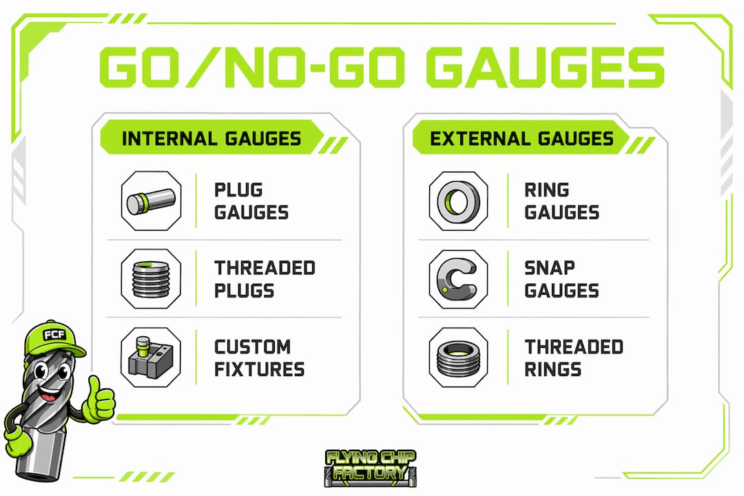
Snap gauges use an open frame with two fixed gaps. A single lateral motion checks both Go and No-Go in one action, which is why they dominate high-volume external checks. The tradeoff: they sample a narrow axial band, so a bent shaft can still pass if the gauge only contacts the straight section.

Thread gauges (threaded plug and ring) verify pitch diameter and thread form. The Go ring must engage fully; the No-Go must not engage more than two turns.
Custom functional fixtures replicate an assembly interface. They check multiple features simultaneously and are the right call when a part must fit a specific mating component, not just a nominal dimension.
| Feature type | Example part | Preferred gauge | Why |
|---|---|---|---|
| Internal bore | Kickstand pivot hole | Plug/pin | Full-length form check |
| External shaft | Axle OD | Ring | Circumferential contact |
| External shaft, high volume | Production shaft run | Snap | Single-action speed |
| Threaded feature | Footpeg stud | Thread plug/ring | Pitch diameter and form |
| Multi-feature assembly interface | Kickstand bracket | Custom fixture | Simultaneous fit check |
Pro Tip: Snap gauges are the right choice for external shafts once you're past first article. For first-article or suspect parts, use a ring gauge — it will catch barrel-shaped or tapered shafts that a snap gauge misses.
When do go/no-go gauges beat a CMM, and when do you need both?
Gauges are for fast, functional pass/fail. CMMs are for measured, diagnostic data. The practical answer is: use both when assembly function and traceability both matter.
The key issue is Rule #1. A CMM program that measures diameter at several cross-sections can report every point within tolerance and still miss a part that violates the MMC perfect-form boundary. Physical gauges verify the full MMC envelope in a way that most CMM programs do not do automatically unless specifically programmed for it.
A workable workflow:
- Gate with the gauge at the machine or incoming inspection. Fast, cheap, catches obvious failures.
- Log with the CMM on first articles, periodic audits, or when a gauge fails a part that looks good visually.
- Escalate a failed gauge to CMM when you need to know why it failed, not just that it failed.
Pro Tip: A bent shaft can pass a snap gauge if the gauge contacts only the straight midsection. Always specify functional length on your gauge drawing so the gauge mirrors the actual assembly engagement zone. A gauge that's shorter than the mating bore is not checking what matters.
False passes from form errors — bent shafts, banana-shaped bores, barrel-shaped pins — are the most common field-escape mechanism when gauge design ignores assembly conditions. The fix is designing the gauge to replicate how the part actually mates.
How do you design and specify a go/no-go gauge for a vendor?
Lead with the complete information set. A vendor who has to ask follow-up questions will add days to your lead time. Include:
- Feature basic size and tolerance band (bilateral or unilateral)
- MMC and LMC values, explicitly called out
- Functional length (the engagement depth the gauge must traverse)
- Datum references and inspection orientation
- Required gauge tolerance class (ASME-referenced, typically Class X or XX for precision work)
- Wear allowance specification on the Go side
- Material and hardness target for contact surfaces
- Plating or coating requirements
- Calibration certificate requirement and re-calibration interval
- Acceptance criteria: describe expected Go/No-Go behavior explicitly
Gauge tolerance is commonly set at roughly 10% of the part tolerance, with an additional wear allowance built into the Go gauge because it sees far more friction than the No-Go side. Tighter gauge tolerances reduce false rejects but raise manufacturing cost — a real tradeoff worth discussing with your machinist before finalizing the spec.
Taylor's Principle governs the gauge geometry: the Go gauge should check MMC of multiple dimensions simultaneously (full-form envelope check); the No-Go gauge should isolate a single dimension. This separation is what prevents false passes from compound form errors.
Drawing callouts to include: datum reference frame, gauge insertion direction arrow, functional length dimension, and a note identifying which surfaces must be checked simultaneously.
What to send with your RFQ: CAD view or 2D drawing, sample part if available, and written acceptance criteria stating exactly what "pass" looks like.
Pro Tip: Always specify a wear allowance on the Go gauge. Without it, a worn Go gauge accepts parts that are actually oversize, and those parts will fail in assembly. A common starting point is 5% of part tolerance added to the Go gauge as a wear offset.
What materials, heat treatment, and calibration intervals should you specify?
Hardened steel is the standard for most shop gauges. Carbide contact surfaces extend service life dramatically on high-cycle runs but cost more to manufacture and are brittle under impact. Ceramic inserts appear in specialized metrology applications but are rarely cost-justified for short-run production gauges.
| Material | Typical hardness | Wear resistance | Relative cost | Best for |
|---|---|---|---|---|
| Tool steel (D2, O1) | min. 60 HRC contact faces | Good | Low | Prototype, short run |
| Carbide (WC) | — | Excellent | High | High-volume production |
| Ceramic | Very high | Excellent | Very high | Precision metrology |
Calibration requirements per ASME guidance:
- Require a traceable calibration certificate on first delivery, referencing NIST-traceable standards.
- Set re-calibration intervals based on usage. High-frequency shop gauges often move from monthly to weekly intervals as cycle counts climb.
- Log each calibration event with the gauge ID, date, technician, and measured values.
- Retire or rework a Go gauge when wear causes it to accept parts at or beyond the MMC limit.
Pro Tip: Store gauges in a temperature-controlled environment and never leave them on a machine surface. Thermal expansion from a warm part or machine bed can cause a gauge to read tight, generating false rejects on perfectly good parts.
How do you order custom gauges and what drives cost?
Lead time and price depend on five factors: feature complexity, material and hardness, gauge tolerance class, calibration certificate requirement, and quantity.
| Order type | Rough lead time | Key cost drivers |
|---|---|---|
| Single prototype gauge | 5–10 business days | Setup, material, tight tolerances |
| Small batch (5–20 gauges) | 10–15 business days | Plating, certs, fixture time |
| Full production set | 3–5 weeks | Custom fixtures, calibration, quantity |
Plating, custom functional fixtures, and tight gauge tolerances (Class XX) are the three factors most likely to extend lead time beyond the baseline. Discuss these upfront.
Order checklist:
- 2D drawing with all callouts from the spec list above
- Feature tolerance and MMC/LMC values
- Sample part (strongly recommended for custom fixtures)
- Required calibration certificate and standard reference
- Target delivery date and acceptable lead time
Spec templates and vendor checklist you can copy into an RFQ
Template A: Single-feature plug or ring gauge
- Feature ID and drawing revision
- Basic size, tolerance (e.g., Ø25.000 +0.025/−0.000)
- MMC / LMC explicit values
- Functional length
- Datum references
- Gauge tolerance class (e.g., ASME Class X)
- Wear allowance on Go side
- Material: tool steel, min. 60 HRC contact faces
- Plating: none / hard chrome (specify)
- Calibration cert required: yes/no, NIST-traceable
- Acceptance criteria: Go enters full functional length; No-Go does not enter
Template B: Multi-feature functional fixture gauge (Taylor's Principle)
All fields from Template A, plus:
- List of features checked simultaneously on Go side
- List of features isolated on No-Go side
- Assembly orientation drawing or sketch
- Mating part sample to be provided for fit verification
Vendor checklist for delivery acceptance:
- Confirm gauge manufacturing tolerance class matches PO
- Calibration certificate included with shipment
- Wear allowance documented on certificate
- Storage and handling instructions provided
- Estimated service life in cycles stated
Pro Tip: Ask the vendor to provide a "proof-fit" run on your sample part before shipping the full order. One confirmed fit check at the shop saves a round-trip return if the functional length was misread.
Flying Chip Factory machines custom gauges with direct machinist access
Short-run gauge programs fail most often at the communication step, not the machining step. Flying Chip Factory solves that by giving you direct access to the machinist quoting and cutting your gauges, not a sales layer that relays specs.

The shop handles custom Go/No-Go plug gauges, ring gauges, and functional fixture gauges for prototype and short-run programs out of Athens, Alabama. Hardened contact surfaces, on-request calibration certificates, and iterative revisions tied to your part development are all part of the service. If you're developing a motorcycle component or a CNC prototype with tight fits, the shop's in-house parts experience means your gauge spec gets reviewed by someone who has already solved similar tolerance problems on real production parts.
To get a quote, send your 2D drawing, feature callouts, and sample part (if available) through flyingchipfactory.com. Attach the spec templates from this guide directly to your RFQ. Prototype gauge turnaround is typically within two weeks depending on material and calibration requirements.
Key Takeaways
Go/No-Go gauges provide unambiguous pass/fail verification of GD&T Rule #1 MMC/LMC boundaries, and specifying functional length, datum callouts, gauge tolerance class, and a wear allowance on the Go side is what separates a gauge that works from one that creates escapes.
| Point | Details |
|---|---|
| Gauge tolerance sizing | Set gauge tolerance at roughly 10% of part tolerance; add wear allowance to the Go side. |
| Taylor's Principle | Go gauge checks multiple dimensions simultaneously; No-Go isolates one dimension to prevent false passes. |
| CMM pairing | Physical gauges verify the MMC envelope in ways CMM programs often miss; use both for critical features. |
| Calibration requirement | Require a NIST-traceable calibration certificate on first delivery; adjust re-calibration interval by usage frequency. |
| Flying Chip Factory | Supplies CNC-machined custom gauges and functional fixtures with direct machinist access for prototype and short-run programs. |
What shop experience actually teaches about gauge specs
The conventional wisdom says "just tolerance the gauge tighter and you'll be fine." It's not wrong, but it misses the more common failure mode: the gauge is perfectly made and perfectly calibrated, and it still lets bad parts through because the functional length was never specified.
Most false passes trace to two omissions: missing functional length and absent datum callouts. A gauge that's 10mm shorter than the mating bore engagement depth will pass a bent shaft every time. The shaft looks straight at the gauge contact zone and curves past it. That part goes into assembly, binds, and nobody connects it to the gauge spec.
Flying Chip Factory builds CNC-machined kickstands and other motorcycle components to tight fits, which means the shop has seen this exact failure. A kickstand pivot shaft passed a plug gauge during incoming inspection and failed to rotate freely in the bracket. The gauge was correct for the nominal diameter. It was not long enough to catch the taper that developed over the last 15mm of the shaft. The fix was a revised gauge drawing with functional length explicitly called out and a datum reference that locked inspection orientation.
Three rules the shop follows on every gauge order: request a proof-fit run on a sample part before full delivery, ask for a calibrated sample gauge on the first order, and engage the machinist before the drawing is finalized when tolerances are tighter than ±0.001 inch. That last one saves more time than any other single step.
Standards and references worth bookmarking
- ASME Y14.5 — the governing GD&T standard; defines Rule #1, MMC, LMC, and feature-of-size requirements that drive gauge design.
- ASME Y14.43 — dimensioning and tolerancing for gauging; the primary reference for gauge tolerance classes and gage maker tolerance tables.
- ASME B89 series — dimensional metrology standards covering calibration traceability and measurement uncertainty.
- GD&T Basics: Go/No-Go Gaging and Rule #1 — clear applied explanation of MMC envelope verification and why physical gauges are still needed alongside CMMs.
- Tyler Engineering: Go/No-Go Gauge Design — practical worked examples on gauge tolerance choices and false-reject rate tradeoffs.
- MechTalk Academy: Taylor's Principle — concise explanation of Go vs No-Go geometry rules and why they matter for multi-feature gauges.
- BUET IPE 381: Gauges and Gauge Design — reference material covering gauge tolerance allocation, wear allowance practice, and design calculations.
For calibration traceability requirements, open ASME B89 first. For gauge tolerance class selection and gage maker tolerance tables, go to ASME Y14.43. For Rule #1 and MMC/LMC boundary definitions, ASME Y14.5 is the primary source.