
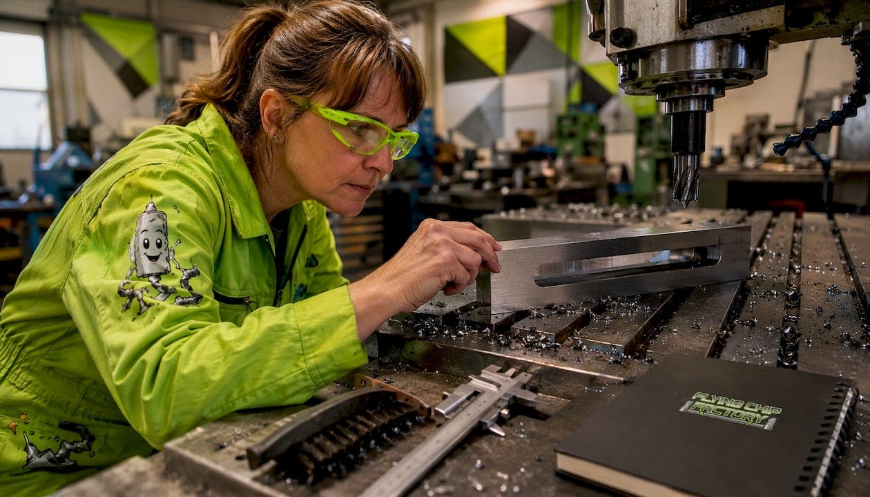
Slot machining is the process of cutting linear grooves, keyways, channels, and undercut profiles into a workpiece, and the fastest reliable path to a good slot is matching your cutter family to the slot geometry before touching feeds and speeds. For most jobs: use a slot mill or side-and-face cutter for long open slots, an end mill for short closed pockets, and a T-slot cutter for undercut profiles. Start conservative on feed per tooth, run multi-pass or trochoidal for deeper slots with high depth-to-width ratio, and verify rigidity before the first cut.
Quick setup checklist before you cut:
- Select cutter family based on slot type (open/closed, depth-to-width ratio, length).
- Set starting fz at roughly 50–60% of the manufacturer's recommended chip thickness, then adjust after the first pass.
- Confirm workholding resists side loads, check arbor runout, and verify chip evacuation path.
Escalate to plunge milling or trochoidal toolpaths when depth exceeds 2× cutter diameter, when chatter appears at conservative parameters, or when the slot geometry prevents adequate chip clearance.
Table of Contents
- What slot machining is and when you need it
- Core slot machining techniques and where each excels
- How to choose the right cutter for your slot
- Feeds, speeds, depth of cut, and chip thickness rules
- Toolpath strategies and CAM settings that actually work
- Workholding, coolant, and chip evacuation
- Material-specific starting points and failure modes
- How to machine T-slots step by step
- Troubleshooting chatter, deflection, and poor finish
- Flying Chip Factory's shop-proven approach to slot jobs
- Key Takeaways
- Why conservative starting parameters are worth the discipline
- Useful sources and further reading
- Flying Chip Factory machines your slots right the first time
What slot machining is and when you need it
Slot milling is a milling operation where the cutter removes material along a linear or curved path to produce a groove with defined width, depth, and length. It differs from face milling (which cuts a flat surface) and peripheral milling (which cuts along the cutter's outer edge) primarily in axis orientation: the cutter engages on both its peripheral and end-cutting edges simultaneously, generating side loads that standard setups must account for.
Common slot types and the geometry triggers that change your method:
- Open slot: Both ends accessible. Side-and-face cutters and slot mills excel here because the cutter can enter and exit freely.
- Closed slot / pocket: One or both ends blind. Requires an end mill with center-cutting capability or a plunge entry.
- Keyway: Narrow, precise, typically 1/4 to 1/2 the shaft diameter in width. Woodruff/keyseat cutters for curved-bottom keyways; end mills or slot mills for straight-sided.
- T-slot: Requires a two-stage operation — straight slot first, then undercut pass with a T-slot cutter.
- Woodruff/keyseat: Curved-bottom profile cut with a keyseat cutter on an arbor; depth-to-width ratio is fixed by the cutter geometry.
Quick decision cues:
- Short closed slot or pocket: end mill, multi-pass.
- Long open slot, production volume: side-and-face cutter on an arbor.
- Deep narrow groove where end-mill overhang causes chatter: slot mill.
- Undercut profile: T-slot cutter or form cutter, staged operation.
- Multiple parallel slots in one pass: gang milling setup.
Core slot machining techniques and where each excels
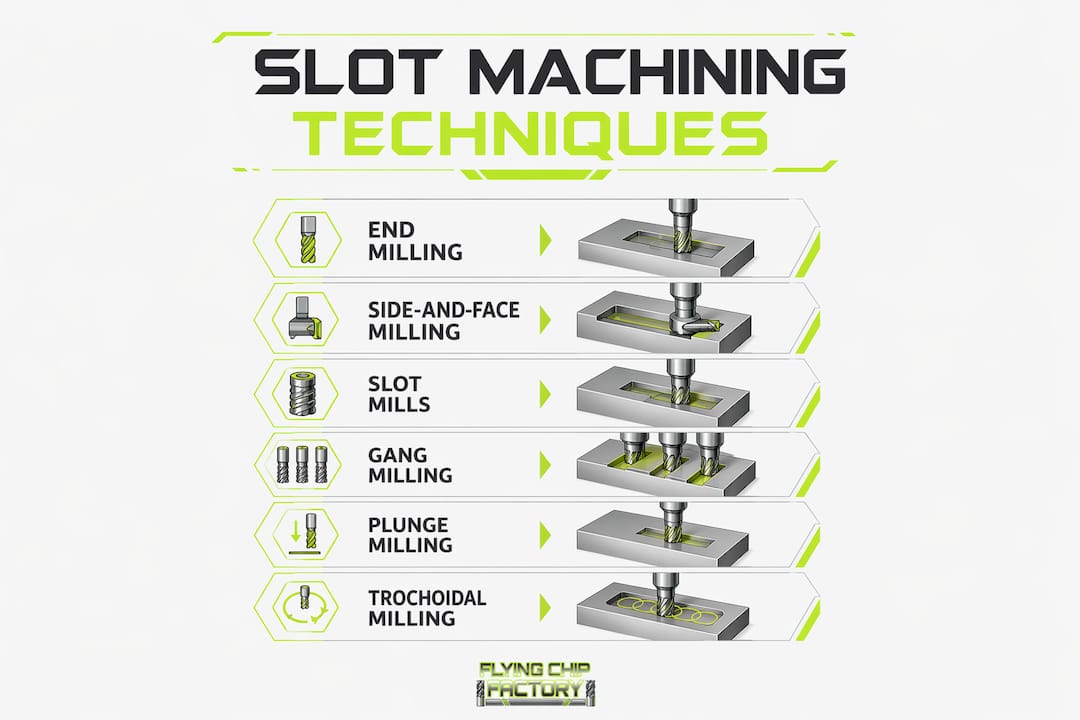
End milling (full slotting)
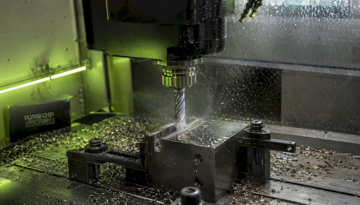
End milling is the most common starting point for CNC slot cutting. The cutter engages 180° of its diameter, which means every tooth alternates between cutting and air — a demanding condition that limits depth of cut and chip load compared to peripheral milling. It works well for short slots, blind pockets, and situations where you need flexibility to change slot width by adjusting the toolpath. The limitation is overhang: once you exceed about 3× diameter in stick-out, deflection and chatter become the dominant problem.
Side-and-face milling
Side-and-face cutters outperform end mills for long, deep open slots in stable, high-volume setups. The multi-edge design distributes cutting forces more evenly, and the arbor support keeps the cutter rigid across the full slot length. The trade-off is flexibility: side-and-face cutters are fixed-width tools, so changing slot width means changing the cutter. They also can't handle closed-pocket geometries.
Slot mills
Slot mills are the underutilized option that machinists reach for too late. Slot mills carry many cutting edges around their circumference, accept arbor support to reduce overhang, and can reach into deep narrow grooves where a standard end mill would deflect or chatter. They're particularly effective in 5-axis side-approach situations and anywhere interference prevents a straight-down entry. The caveat is that arbor assembly and spacer parallelism must be correct — errors here cause runout and unstable groove width.
Gang milling
Gang milling mounts multiple cutters on a single arbor to cut several slots simultaneously. It's a production-oriented strategy that multiplies throughput but demands a rigid spindle, adequate torque, and precise arbor setup. Gang milling is rarely worth the setup time for one-off or short-run work; it pays off when you're running the same part in volume.
Plunge milling
Plunge milling drives the cutter axially into the workpiece rather than radially. This converts the dominant bending load into axial compression, which the spindle and toolholder handle far better. It's the right call for deep slots where radial deflection is unacceptable, and for roughing passes before a finishing end-mill pass cleans up the walls.
Trochoidal milling
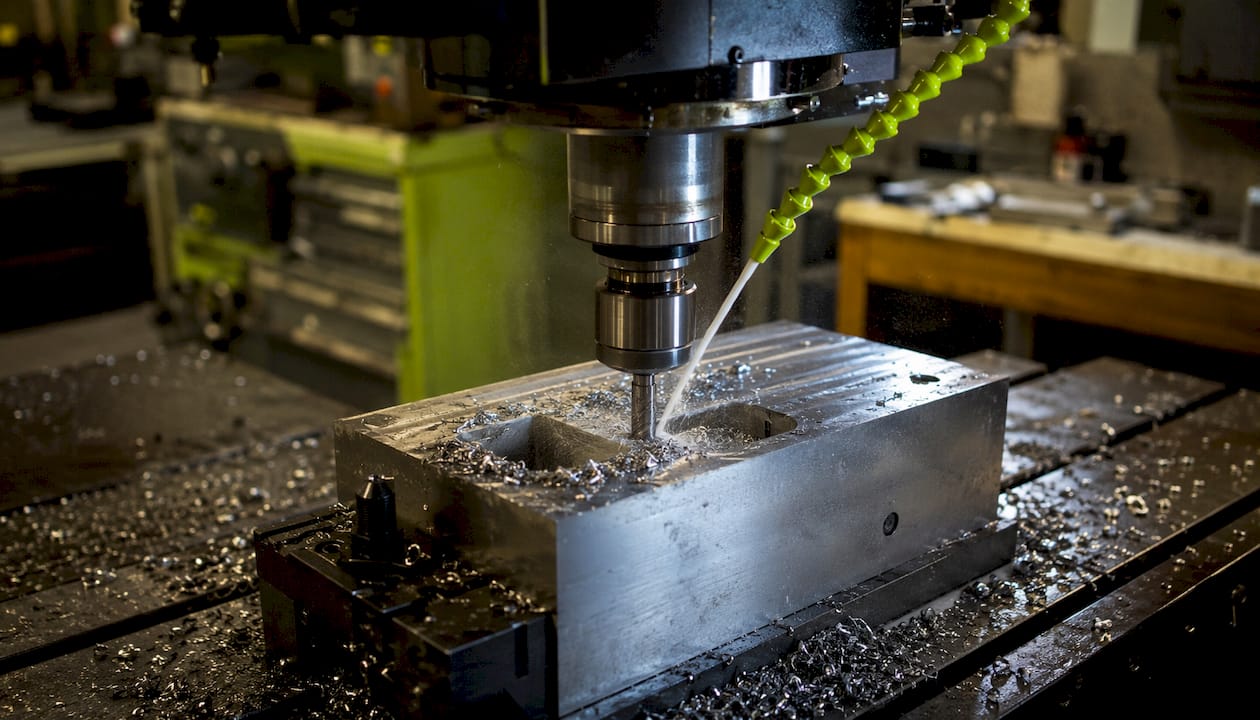
Trochoidal paths move the cutter in a circular arc while advancing along the slot axis, keeping radial engagement constant and low. Trochoidal milling enables higher feed rates and better chip evacuation than full slotting, particularly in deep pockets and long slots. Most modern CAM packages (Mastercam, Fusion 360, Siemens NX) include a trochoidal or "dynamic milling" strategy.
Pro Tip: When switching from full slotting to trochoidal on an existing program, reduce the radial stepover to 10–15% of cutter diameter as a starting point, then increase until you see chatter or chip-evacuation problems.
How to choose the right cutter for your slot
The first decision is cutter family; the second is diameter. A general rule: size the cutter diameter slightly smaller than the slot width, leaving a small amount for a finishing pass.
| Cutter Family | Typical Slot Width Range | Best Slot Type | Key Constraint |
|---|---|---|---|
| End mill (solid carbide) | 0.25–1.0 in. | Short closed slots, pockets | Overhang limit about three times the cutter diameter |
| Slot mill (arbor-mounted) | 0.250–0.500 in. | Deep narrow grooves, interference fits | Arbor runout must be <0.0005 in. |
| Side-and-face cutter | 0.250–1.00 in. | Long open slots, production runs | Fixed width; needs arbor support |
| T-slot cutter | Per ANSI T-slot standard | T-slots, undercuts | Staged operation required |
| Woodruff/keyseat cutter | Per ANSI keyseat standard | Curved-bottom keyways | Fixed geometry per cutter number |
| Indexable end mill | 0.500–2.00 in. | Large slots, roughing passes | Less suitable for tight tolerances |
Solid vs. indexable: Solid carbide end mills give better accuracy and surface finish for slots under 0.750 in. Indexable tools make sense for larger slots and roughing where insert replacement is faster than regrinding.
Coatings: AlTiN or TiAlN for steels and stainless; uncoated or ZrN for aluminum (AlTiN can cause built-up edge in aluminum). TiSiN or AlCrN for titanium and high-temp alloys.
Corner radius: A corner radius of 0.010–0.030 in. on an end mill significantly reduces chipping at the slot floor and extends tool life. Use it unless the slot geometry requires a sharp corner.
Pro Tip: For deep narrow slots, slot mills reduce overhang and chatter compared to long-reach end mills. If you're stacking significantly more than three times the diameter in reach, a slot mill on an arbor is often the better call.
Feeds, speeds, depth of cut, and chip thickness rules
Chip thickness (fz, feed per tooth) is the single most important parameter in slotting. Too low and the cutter rubs instead of cuts, generating heat and accelerating wear. Too high and you overload the teeth, causing chipping or breakage.
Converting surface speed to RPM:
RPM = (Vc × 3.82) / D
Where Vc is cutting speed in surface feet per minute (SFM) and D is cutter diameter in inches.
Starting parameters by material (conservative shop starting points):
- Aluminum (6061-T6), 0.500 in. solid carbide end mill: Vc = 800–1,000 SFM, fz = 0.003–0.005 in./tooth, ap (axial) = 0.5× D, ae (radial/full slot) = 1.0× D.
- Mild steel (1018/A36), 0.500 in. solid carbide end mill: Vc = 300–400 SFM, fz = 0.002–0.003 in./tooth, ap = 0.25× D, ae = 1.0× D.
- Stainless steel (304), 0.500 in. solid carbide end mill: Vc = 150–200 SFM, fz = 0.0015–0.002 in./tooth, ap = 0.20× D, ae = 1.0× D.
- Cast iron (gray), 0.500 in. solid carbide end mill: Vc = 250–350 SFM, fz = 0.002–0.003 in./tooth, ap = 0.25× D, ae = 1.0× D.
Sandvik Coromant gives a starting maximum chip thickness of 0.12 mm (0.005 in.) for full slotting with geometry M30, and recommends reducing fz for deeper slots to maintain that chip thickness as engagement changes.
Chip thinning: When ae drops below 50% of cutter diameter (as in trochoidal passes), the actual chip thickness is less than fz. Compensate by increasing fz to maintain the target chip thickness. Most CAM software handles this automatically when you input the correct cutter geometry.
Overhang and deflection: Every additional 0.5× D of overhang beyond 3× D roughly doubles deflection at the cutter tip. If you can't shorten the tool, reduce fz by 20–30% and consider switching to a trochoidal path to lower radial engagement.
Entry strategy: Ramp or helical entry is preferred for closed slots. Straight plunge is acceptable only with a center-cutting end mill and at reduced feed (50% of cutting feed). Never plunge a side-and-face cutter or slot mill.
Toolpath strategies and CAM settings that actually work
Single-pass vs. multi-pass
Single-pass full slotting is fast but puts maximum load on the cutter. It's acceptable for shallow slots (ap ≤ 0.5× D) in aluminum and soft materials with a rigid setup. For anything deeper, or in steels and stainless, multi-pass is the safer default: rough to within 0.010–0.020 in. of final width and depth, then take a dedicated finishing pass at reduced fz and ae.
Trochoidal and high-efficiency paths
Trochoidal toolpaths maintain constant cutter engagement, which keeps cutting forces predictable and chip evacuation consistent. In practice, this means you can run higher feed rates than full slotting while generating less heat. The path takes longer to program but pays back in tool life and surface finish, especially in stainless and titanium.
Climb vs. conventional milling
Climb milling (cutter rotation matches feed direction) produces a better surface finish and lower cutting forces in most CNC slot cutting situations. Conventional milling is sometimes preferred for the first pass on a rough or scaled surface because the chip starts thin and thickens, reducing the chance of the cutter digging in. For finishing passes in a slot, climb milling is almost always the right choice.
CAM setup notes
- Use lead-in/lead-out arcs on finishing passes to avoid a witness mark at the entry point.
- For T-slots and undercuts, program the undercut pass as a separate operation with its own tool and feed rate.
- Canned cycles (G12/G13 circular pocket cycles) work for round pockets but are rarely appropriate for linear slots; use full-path toolpaths for better control.
- Set coolant on before the cutter enters the material, not after.
Pro Tip: In Fusion 360 or Mastercam, set the "radial stock to leave" on your roughing pass to 0.010–0.015 in. and run a separate finishing contour at full depth. This gives you a clean wall without a second tool change in most cases.
Workholding, coolant, and chip evacuation
Fixturing checklist
- Clamp as close to the slot location as the geometry allows to minimize workpiece deflection under side loads.
- Use support pads or parallels under thin sections to prevent flexing during the cut.
- For T-slots and keyways, verify parallelism of the slot axis to the machine table travel — a 0.001 in./ft error compounds across a long slot.
- Soft jaws or custom fixtures are worth the setup time on any run longer than 5 parts.
Chip evacuation
Chip re-cutting is one of the fastest ways to ruin a slot finish and accelerate tool wear. Chips that stay in the slot get dragged back through the cut, scoring the walls and loading the cutter. Through-spindle coolant and high-pressure nozzles are the most effective solutions for deep slots where external coolant can't reach the cutting zone. For slitting saws and side-and-face cutters, direct the coolant nozzle to flush chips out of the slot in the direction of cutter rotation.
- Through-spindle coolant: Best for deep slots and small-diameter end mills where external coolant can't reach.
- High-pressure external nozzles: Effective for open slots and side-and-face operations.
- Air blast: Acceptable for aluminum and cast iron; not sufficient for deep steel slots.
- Chip-breaking strategies: Peck cycles or programmed Z-axis retracts at intervals help break chips in deep slots where continuous cutting packs the flutes.
Coolant selection
- Aluminum: flood coolant or mist; avoid AlTiN-coated tools with water-based coolant (use uncoated or ZrN).
- Steels: water-soluble oil at 8–10% concentration.
- Stainless: high-lubricity coolant; through-spindle preferred.
- Titanium: flood coolant at high pressure; never run dry.
- Cast iron: dry or light air blast; flood coolant can cause thermal shock and cracking.
Pro Tip: For deep slots in steel, program a retract-and-blast cycle every 0.100–0.200 in. of depth. It adds a few seconds per pass but prevents chip packing, which is the most common cause of sudden tool failure in deep slot milling.
Material-specific starting points and failure modes
| Material | Starting Vc (SFM) | Starting fz (in./tooth) | Typical ap | Common Failure Mode | Coating |
|---|---|---|---|---|---|
| Aluminum 6061 | 800–1,000 | 0.003–0.005 | 0.5× D | Built-up edge | Uncoated / ZrN |
| Mild steel 1018 | 300–400 | 0.002–0.003 | 0.25× D | Flank wear | TiAlN / AlTiN |
| Stainless 304 | 150–200 | 0.0015–0.002 | 0.20× D | Work hardening | TiAlN / TiSiN |
| Cast iron (gray) | 250–350 | 0.002–0.003 | 0.25× D | Abrasive wear | AlTiN |
| Titanium Ti-6Al-4V | 120–150 | 0.001–0.0015 | 0.20× D | Heat buildup, notch wear | TiSiN / AlCrN |
Aluminum is the most forgiving material for slot machining but the most prone to built-up edge at low speeds. Keep Vc above 600 SFM and use a sharp, polished flute geometry. Chip evacuation is critical because aluminum chips are large and sticky.
Stainless steel work-hardens if the cutter dwells or rubs. Keep the feed up, never let the cutter stop in the cut, and use a sharp tool with a positive rake angle. A dull tool in stainless is a scrapped part.
Cast iron produces abrasive, brittle chips that stay in the slot. Dry cutting or light air blast is preferred; flood coolant risks thermal cracking. AlTiN coatings handle the abrasive wear well.
Titanium has low thermal conductivity, so heat concentrates at the cutting edge. High-pressure flood coolant is non-negotiable. Keep ap conservative and use a trochoidal path to limit engagement time per tooth.
Pro Tip: In stainless steel, a glazed or work-hardened surface on the slot wall indicates the feed was too low; increase feed per tooth and ensure tool sharpness. Rubbing is always worse than cutting in stainless.
How to machine T-slots step by step
T-slots require a staged approach. Trying to cut the undercut in a single pass with a T-slot cutter is the most common mistake — the cutter can't handle the full material removal, and deflection ruins the profile.
- Rough the vertical slot to full depth with a standard end mill. Width should match the neck dimension of the T-slot cutter plus 0.010–0.020 in. clearance.
- Semi-finish the vertical slot if needed to bring walls to within 0.005 in. of final dimension.
- Mount the T-slot cutter on a stub arbor. Verify runout is under 0.001 in. before cutting.
- First undercut pass: Set ap to 50–60% of the T-slot cutter's full depth. Feed slowly (reduce fz by 40–50% from the roughing pass). Climb mill for better finish.
- Finishing undercut pass: Full depth, reduced fz (0.001–0.0015 in./tooth), flood coolant.
- Inspect the undercut profile with a T-slot gauge or a go/no-go gauge matched to the ANSI T-slot standard. Check width, depth, and parallelism to the slot centerline.
T-slot machining requires careful arbor support and staged operations to avoid runout and deflection on the undercut pass. A T-slot cutter with too much overhang will deflect and produce a tapered undercut that fails inspection.
Common pitfalls: Skipping the semi-finish pass leaves too much stock for the T-slot cutter. Using a worn or chipped T-slot cutter produces a rough undercut that won't accept standard T-nuts. Always inspect the undercut width at both ends of the slot — taper is the most common defect.
Troubleshooting chatter, deflection, and poor finish
Symptom: chatter (vibration marks on slot walls)
- Check first: Spindle runout (should be under 0.0002 in. at the collet), arbor assembly tightness, tool overhang.
- Fixes: Shorten tool stick-out, increase fz (a rubbing cutter chatters more than a cutting one), reduce ap, switch to a trochoidal path to lower radial engagement.
- Escalate to: Slot mill on arbor if end-mill overhang is unavoidable; plunge roughing to remove bulk material before a light finishing pass.
Symptom: poor surface finish (torn or rough walls)
- Check first: Tool sharpness, climb vs. conventional setting, chip re-cutting.
- Fixes: Switch to climb milling on the finishing pass, add a spring pass (repeat the finishing pass at the same depth with no additional stock removal), improve chip evacuation.
Symptom: unstable slot width (oversize or variable width)
- Chip re-cutting, runout, and improper arbor assembly are the main causes of unstable groove width. Check spacer parallelism and arbor runout before assuming the program is wrong.
- Fixes: Disassemble and reassemble the arbor, check spacers for burrs or contamination, measure runout after reassembly.
Symptom: tool breakage
- Check first: Entry strategy (plunging a non-center-cutting tool), chip packing, fz too high for depth.
- Fixes: Switch to helical or ramp entry, add peck cycles for chip breaking, reduce fz and verify chip evacuation.
Pro Tip: If chatter appears only at the bottom of a deep slot, the problem is usually tool deflection at full depth, not spindle or workholding. Reduce ap per pass and switch to a trochoidal path before trying anything else.
Flying Chip Factory's shop-proven approach to slot jobs
At Flying Chip Factory, most slot jobs come in as part of a prototype or short-run fixture build, where getting the geometry right on the first part matters more than cycle time. The shop's default approach is to start with a slot mill or solid carbide end mill sized to the slot width, run a trochoidal roughing path, and finish with a single climb-milling pass at reduced fz.
A recent fixture plate job required a series of 0.375 in. wide × 1.250 in. deep slots in 4140 steel. The chosen approach: a 0.360 in. solid carbide end mill running a trochoidal path at 250 SFM and fz = 0.0018 in./tooth, roughing to 0.010 in. stock, followed by a finishing pass at 0.0010 in./tooth. Slot width held to ±0.0005 in. across all 12 slots, and surface finish was consistent enough to skip a secondary grinding operation.
What Flying Chip Factory asks for when quoting a slot job:
- Slot width, depth, and length (with tolerances).
- Open or closed ends, and whether a T-slot or undercut is required.
- Material and heat treat condition.
- Surface finish requirement (Ra or Rz).
- Whether the slot mates with a standard key, T-nut, or custom feature.
Pro Tip: Send a DXF or STEP file with your slot dimensions called out. It cuts quoting time in half and eliminates the most common source of rework: a misread tolerance on a hand-drawn sketch.
Key Takeaways
Reliable slot machining comes down to matching cutter family to slot geometry, setting fz to maintain chip thickness in the correct range, and verifying rigidity before the first cut.
| Point | Details |
|---|---|
| Match cutter to slot type | Use end mills for short closed slots, slot mills or side-and-face cutters for long open slots, and T-slot cutters for undercuts. |
| Start conservative on fz; reduce feed per tooth for deeper slots to maintain proper chip thickness. | |
| Use trochoidal paths for deep slots | Trochoidal toolpaths maintain constant engagement and improve chip evacuation in slots deeper than 2× cutter diameter. |
| Check arbor runout before cutting | Runout above 0.001 in. causes unstable slot width and poor finish; verify after every arbor assembly. |
| Flying Chip Factory for slot work | Flying Chip Factory runs prototype and short-run slot jobs in Athens, Alabama, with direct machinist access for fast iteration. |
Why conservative starting parameters are worth the discipline
There's a temptation in CNC slot cutting to push parameters from the start, especially on a short-run job where setup time feels like the bottleneck. The problem is that slot machining is one of the least forgiving milling operations: the cutter is fully engaged, chip evacuation is constrained, and deflection compounds with depth. A broken tool or a scrapped part on part one costs more time than the conservative first pass ever would.
The recommendations in this guide lean toward starting values that give you a working part on the first attempt, then optimizing from there. That's not timidity — it's how production-proven setups get built. Flying Chip Factory's prototype and short-run focus means the shop rarely has the luxury of a long trial-and-error cycle. The conservative parameters and pre-cut checks described here reflect what actually works when you need the part right the first time, not after three iterations.
The other thing worth saying: trochoidal milling is still underused in small shops. Machinists who learned on full-slotting setups sometimes resist it because it looks slower on the screen. In practice, for any slot deeper than 1.5× cutter diameter in steel or stainless, trochoidal paths almost always deliver better tool life, better finish, and fewer surprises. The cycle time difference is smaller than it looks, and the reduction in broken tools more than compensates.
Useful sources and further reading
These are the primary references used to compile this guide. Each covers a distinct part of the topic:
- Sandvik Coromant — Groove or Slot Milling: The most comprehensive publicly available technical reference for slot milling parameters, cutter selection, and chip-thickness calculations. Start here for parameter derivation.
- Tungaloy — Slot Mills as a Machining Option: Detailed coverage of slot mill advantages, arbor setup, and troubleshooting for unstable groove width. Useful for deep narrow groove applications.
- CNCCookbook — Deep Pocket, Deep Cavity, & Deep Slot Milling: Practical guide to trochoidal and plunge milling strategies, coolant hardware, and CAM setup for deep slots.
- Xometry — Slot Milling: How It Works, Types, Advantages, and Disadvantages: Good overview of slot types, applications, and cutter selection for engineers new to the operation.
- JLCCNC — T-Slot Milling: CNC Tooling, Tolerances & Challenges: Focused reference for T-slot staged operations, arbor setup, and inspection.
- Flying Chip Factory: Contact the shop directly for a quote on prototype or short-run slot machining jobs.
Flying Chip Factory machines your slots right the first time
Slot machining in production or prototyping leaves little room for rework. Flying Chip Factory is a CNC job shop in Athens, Alabama, built specifically for engineers and designers who need tight-tolerance slot work done fast, without the overhead of a large contract shop.

The shop handles open slots, keyways, T-slots, and undercut profiles across aluminum, steel, stainless, and 4140. Direct access to the machinist means tolerance questions get answered in hours, not days, and first-article inspection results come back with the part. No account managers, no communication delays.
If you have a slot job that needs a reliable setup and a quick turnaround, request a quote at Flying Chip Factory. Send your STEP or DXF file with tolerances called out, and the shop will come back with a realistic lead time and price.