

Circularity controls the roundness of a single cross-section. Cylindricity controls the entire cylindrical surface at once, folding in roundness, straightness, and taper across the full length. That's the whole distinction in one sentence, and it drives everything else in this article.
The practical rule follows just as fast: specify cylindricity only when full-length form is function-critical. Otherwise, circularity, runout, or profile will usually get you the same functional result for less inspection cost. Here's the quick sorting logic:
- Cross-section roundness only matters? Use circularity.
- Full-length form (round, straight, no taper) matters, but axis location doesn't? Use cylindricity.
- Axis alignment or location relative to another feature matters? Use runout or position instead.
- Cylindricity is already on the print? Expect a 3D roundness trace or CMM check, not a caliper reading.
Key Takeaways
Cylindricity guarantees full-length cylindrical form by bundling roundness, straightness, and taper into one datum-free tolerance zone, while circularity checks roundness one cross-section at a time.
| Point | Details |
|---|---|
| Core distinction | Circularity checks one cross-section; cylindricity checks the whole surface for roundness, straightness, and taper together. |
| No datums allowed | Both are pure form controls; use runout or position when axis alignment or location matters. |
| Inspection gap | Circularity needs a single roundness trace; cylindricity needs multiple traces or a CMM best-fit cylinder calculation. |
| Diametral checks don't prove form | A consistent caliper reading can hide a lobed or triangular cross-section that fails roundness. |
| Specify the minimum control | Default to circularity or runout unless full-length form is truly function-critical, since cylindricity raises inspection cost. |
Circularity vs Cylindricity: The Formal Geometric Definitions
Circularity, sometimes called roundness, restricts a feature's cross-section to the space between two concentric circles. Picture slicing a shaft perpendicular to its axis at any single point. The trace of that slice has to fit inside an annular ring of the specified width. Nothing outside that slice matters. A shaft can be perfectly round at every station you check and still be a banana underneath, because circularity never looks past the plane it's measuring.
Cylindricity works differently. It restricts the entire surface, not one slice, to the space between two concentric, coaxial cylinders running the full length of the feature. That single tolerance zone has to contain every cross-section simultaneously, which means cylindricity bundles three separate error sources into one number:
- Circularity at every cross-section along the length.
- Straightness of the surface elements (generators) running parallel to the axis.
- Taper, meaning any gradual change in diameter from one end to the other.
Here's the number that trips people up: a shaft can score a perfect 0.0005 inch on circularity at every single cross-section checked and still fail a 0.001 inch cylindricity call, because the axis itself curves or the diameter tapers along the length. Circularity is blind to that. Cylindricity isn't.
Neither tolerance references a datum. Both are pure form controls, meaning they say nothing about where the feature sits relative to anything else on the part, and nothing about its size. Size is governed separately by the dimensional limits and Rule #1. If you need the axis to line up with a bore somewhere else on the part, form controls won't get you there. That's a job for runout or position, which we'll get to shortly.
How Do You Call Out Circularity and Cylindricity on a Drawing?
The feature control frame for circularity is a small circle symbol followed by the tolerance value in a box: a callout like ⌀0.001 for circularity means the cross-section has to fit inside a 0.001-inch-wide ring at every station checked. Cylindricity uses a symbol that looks like a circle tipped with two small vertical lines, formatted the same way: symbol, then tolerance value, no exceptions.
The single most common drawing error on cylindricity calls is adding a datum reference to the feature control frame. Don't. Form controls, by definition, cannot reference a datum, so a cylindricity frame with a datum letter in it is asking the machine shop and the inspector to satisfy an instruction that doesn't legally exist under ASME Y14.5 or the equivalent ISO geometric tolerancing standards. Quoting engineers will flag it, and it usually means a redlined print comes back before the job even starts.
A few callout conventions worth locking in:
- Tolerance values are stated in the same linear units as the rest of the drawing (inches or millimeters), never mixed.
- Decimal places should match your general tolerance block. Don't specify 0.0005 inch cylindricity on a drawing whose title block reads two-place decimals.
- If the tolerance zone diameter is meant to apply per unit length (a less common but valid practice), that has to be stated explicitly beneath the feature control frame.
Pro Tip: Before you release a print with a cylindricity callout, ask yourself whether you actually need the taper and straightness control it bundles in, or whether you just need the part round. If it's the latter, swap it for circularity and save your supplier (and your budget) the CMM time.
How Do You Measure Circularity and Cylindricity?
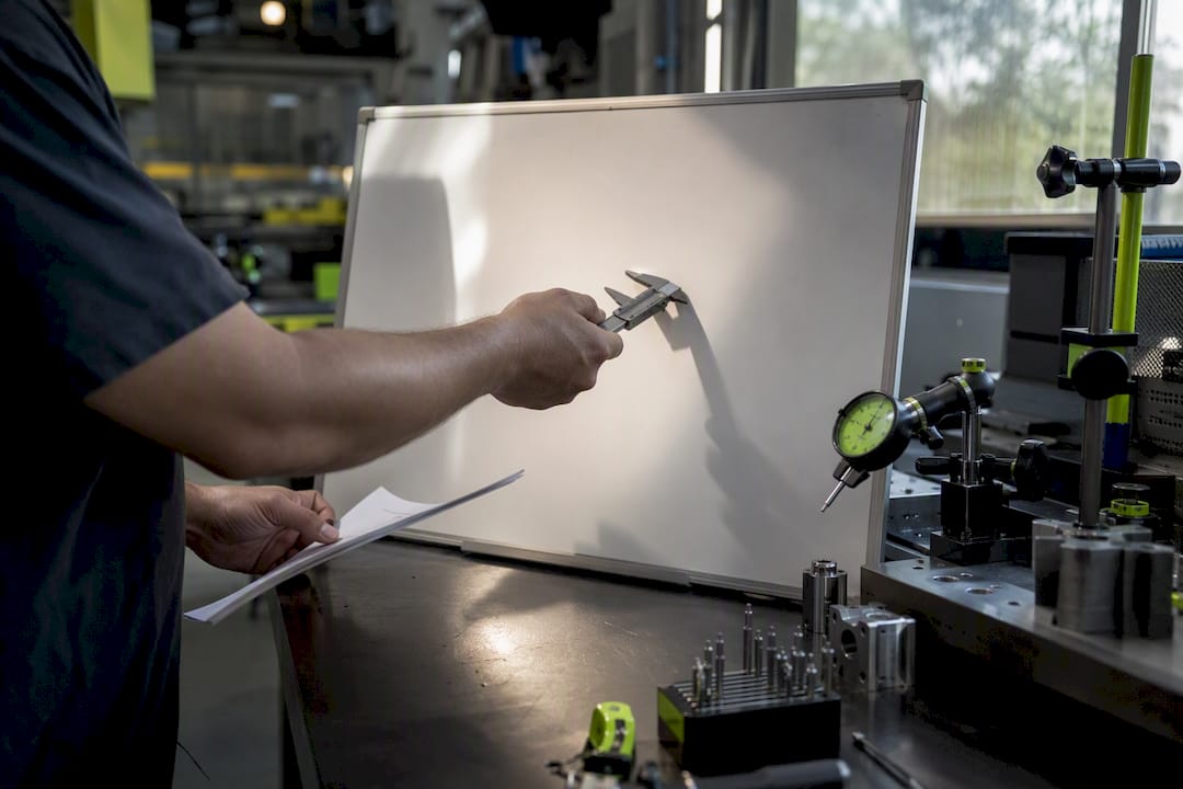
Circularity inspection is comparatively simple. A roundness tester rotates the part (or the probe) around the axis at a single cross-section and generates a polar plot of the surface trace, which is compared against two concentric circles at the specified spacing. That single-section trace is what actually verifies roundness. A diameter check with calipers or a micrometer does not, because two points 180 degrees apart can read identical diameters on a part that's a perfect triangle with rounded corners (a Reuleaux shape). Diametral checks measure size, not form.
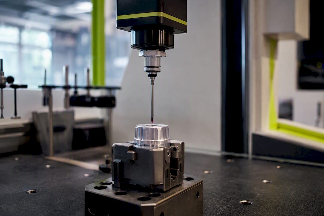
Cylindricity inspection is a bigger lift. Because the tolerance zone has to contain the whole surface, verification generally requires one of two approaches:
- Multiple roundness traces at several cross-sections, stitched together to check for taper and generator straightness in addition to per-slice roundness.
- Full CMM point-cloud collection, where the software computes a best-fit cylinder from the collected points and reports the radial separation between the two coaxial cylinders that just contain the data.
There's a measurement mistake worth flagging directly: rotating a part between centers on a lathe or bench setup and watching a dial indicator does not measure cylindricity, or even circularity, on its own. That setup measures runout, which mixes form error with any misalignment between the part's actual axis and the center axis you rotated it on. If the part is bowed but you're rotating it true to its own bent centerline, runout can read artificially low even though the form is genuinely bad.
Resource-wise, the gap between the two is real. A single-plane roundness check on a dedicated roundness tester takes a few minutes once the part is fixtured. A full cylindricity evaluation on a CMM, with enough cross-sections to trust the best-fit result, can run several times longer and demands equipment most job shops don't keep on the floor for routine work. That gap is exactly why cylindricity calls almost always show up as a line item on a quote, separate from general dimensional inspection.
When Should You Specify Circularity Instead of Cylindricity?
Here's a contrived but useful example: imagine a shaft ground perfectly round at five different stations along its length, each cross-section a flawless circle. Now imagine the axis connecting those five circles has a gentle bow in it, like a very slightly bent arrow. Every single circularity check passes. Cylindricity fails, because the tolerance zone has to be one straight coaxial cylinder pair covering the entire length, and a bowed axis won't fit inside a straight zone no matter how round each slice is. This is the exact scenario study guides use to illustrate that cylindricity is not circularity repeated over a length, it's a genuinely distinct requirement.
Real parts sort into these categories pretty cleanly:
- Sealing journals and O-ring grooves: circularity is usually enough. The seal only cares about round contact at the sealing plane, not what the shaft does three inches away.
- Bearing surfaces on a short shaft section: circularity, sometimes paired with a size tolerance, covers most bearing loads.
- Long sliding shafts moving through a bushing or bore over their full length: cylindricity earns its cost here, because a taper or bow will bind the slide even if every cross-section reads round.
- Features that must align with a bore or a bolt pattern elsewhere on the part: neither form control helps. You need runout or position, since form controls can't reference a datum in the first place.
The decision checklist boils down to four questions, asked in order:
- What does this feature actually need to do?
- Does full-length straightness or taper affect that function, or only the local cross-section?
- Does the feature's location or axis alignment relative to another feature matter?
- Given the answers above, what's the least restrictive control that still guarantees the function?
Pro Tip: Answer question four honestly before you release the print. Every step up in tolerance strictness, especially the jump from circularity to cylindricity, adds inspection time that shows up in your quote. Don't pay for a control your part doesn't functionally need.
Common Mistakes That Drive Up Cost Without Adding Function
The single most expensive habit we see on incoming prints is defaulting to cylindricity out of caution, on the theory that a stricter-sounding tolerance is automatically safer. Practitioners generally warn against this: cylindricity drives up inspection complexity and cost, and if circularity or runout would have guaranteed the function just as well, the extra strictness bought nothing but a bigger invoice.
The second mistake is adding a datum reference to a form control, which as covered above simply isn't a legal instruction under the standard and forces a print revision before work can start. The third is treating a micrometer or caliper reading as proof of roundness. It proves size, not form, and a triangular or lobed part can read a consistent diameter at every station checked.
A few habits fix most of this before it costs you anything:
- State the functional requirement on the RFQ, not just the tolerance symbol. Tell your supplier why the feature needs to be round or cylindrical.
- Specify the expected inspection method directly on the print or in the quote request.
- Ask whether total runout or profile of a surface would satisfy the function at lower verification cost, particularly when location matters anyway.
- Favor fixturing and machining sequences (single setup, minimal part flip) that naturally produce good form, rather than relying on inspection to catch problems after the fact.
Where Runout, Concentricity, and Profile Fit In
Form controls like circularity and cylindricity never reference a datum, which means they can't tell you anything about how a feature sits relative to the rest of the part. That's where the composite controls take over.
Circular runout checks a single cross-section's variation as the part rotates true to a datum axis, catching both roundness error and axis misalignment in one reading. Total runout does the same across the full surface, functioning as cylindricity's datum-referenced cousin. Profile of a surface is the most flexible option: it can control form, orientation, and location all in one callout, which makes it useful when a feature needs cylindricity-like form control and a defined position, though it can be overkill if only form is actually needed.
The mapping is simple: need local roundness, use circularity. Need whole-surface form with no location tie-in, use cylindricity. Need the feature to rotate true to another feature, use runout. Need form plus a specific location, use profile.
How Flying Chip Factory Handles Circularity and Cylindricity Callouts
When a print lands on our floor with a cylindricity callout, the first thing we look at is whether the drawing states an inspection method. If it doesn't, that's the biggest source of quoting uncertainty we run into, because a vague cylindricity call could mean anything from a single roundness trace to a full CMM point-cloud study with a specific sample count. We ask for the acceptance method up front rather than guessing and re-quoting later.
We've walked customers back from cylindricity to circularity more than once, including on our own kickstand line for electric dirt bikes, where the pivot bore needed to be round for smooth bushing engagement but didn't need whole-length straightness control given its short bearing length. That swap kept the part functional and cut inspection time on every unit.
A print that includes these four items rarely comes back for revision:
- Required acceptance method (roundness trace, CMM best-fit, or comparator).
- Number of samples to be measured.
- Fixture or setup description if the feature is hard to access.
- Expected measurement equipment, if a specific uncertainty level matters.
Pro Tip: If you're not sure whether your part needs circularity or cylindricity, describe the function in plain language on the RFQ. A machinist can usually translate that into the right, least-expensive tolerance faster than a spec sheet can.
Flying Chip Factory's shop experience shows cylindricity often raises quoting and inspection costs for prototype and short-run work; clear print callouts and expected inspection methods reduce iteration and cost.
Ready to get a straight answer on which tolerance your part actually needs? Request a quote from Flying Chip Factory and talk directly with the machinist who'll run the job, not a sales layer that has to relay your questions back and forth.
A Shop-Centered Take on Choosing the Right Form Control
The conventional GD&T textbook treatment stops at geometry: here's a circle, here's a cylinder, memorize the difference. That's necessary but insufficient. The real skill is knowing which control your function actually demands, because every step up in strictness gets billed to somebody, and it's usually the part buyer.
Cylindricity gets over-specified more often than any other form tolerance we see, typically out of caution rather than genuine need. The fix isn't a stricter default. It's asking what the part does before touching the feature control frame. A short bearing journal rarely needs whole-length straightness control. A long sliding shaft through a tight bore usually does.
If you take one thing from this, let it be that the cheapest tolerance that guarantees function beats the strictest one every time, and knowing the difference between circularity and cylindricity is what lets you make that call with confidence instead of guessing.
— Drake
Sources
- Roundness, cylindricity, coaxiality, concentricity, runout and total runout — Crossco
- Cylindricity — GD&T Basics
- GDT: Cylindrical Specifications — efunda
- Circularity and Cylindricity — OpenExamPrep