
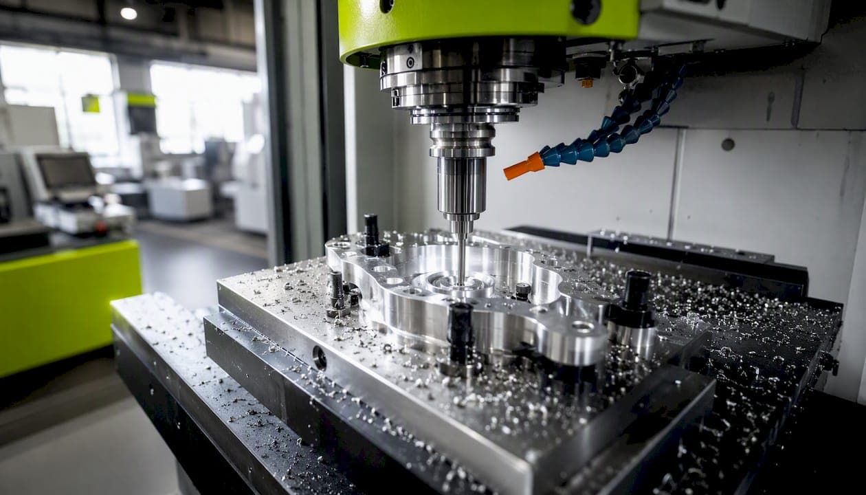
Tight tolerance machining means holding dimensional accuracy beyond what standard CNC processes deliver by default. In practice, most shops treat anything tighter than ±0.005" (±0.13 mm) as entering tight territory, with ±0.001" (±0.025 mm) and below considered high precision, and ±0.0005" (±0.013 mm) pushing into ultra-precision territory that demands grinding, lapping, or specialized equipment. Before you tighten a single callout on your drawing, three things need to happen:
- Identify functional features first. Only features that directly affect fit, function, or assembly should carry tight callouts. Everything else should stay at standard tolerances.
- Call out GD&T datums explicitly. A tight size tolerance without a controlled datum reference is ambiguous and often unmeasurable in a repeatable way.
- Check shop and process capability before tightening the print. A tolerance your shop cannot measure reliably is a tolerance it cannot hold reliably.
Key takeaways
Tight tolerance machining pays off when it is targeted at functional features, specified with GD&T, and backed by a measurement plan that matches the tolerance level.
| Point | Details |
|---|---|
| Tight starts at ±0.005" | Most production environments treat ±0.005" (±0.13 mm) as the entry point for tight tolerance work. |
| Target critical features only | Apply tight callouts to the three to five features that directly drive fit, function, or assembly. |
| GD&T over bilateral dimensions | ASME Y14.5 controls feature relationships, not just sizes, which is what tight assemblies actually need. |
| Measure before you commit | The 10:1 gauge rule means a ±0.001" tolerance requires a gauge resolving to 0.0001"; confirm this before quoting. |
| Flying Chip Factory | Direct machinist access means DFM review, first-article inspection, and tight-tolerance CNC work without the communication delay. |
What does "tight tolerance" actually mean in CNC work?
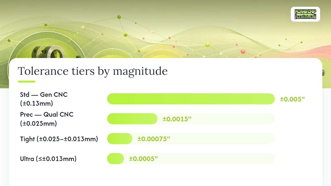
The phrase gets used loosely, so here are the numbers that actually matter. CNC precision machining commonly achieves tolerances from ±0.002" down to ±0.0005" or better, and tightening from ±0.005" to ±0.001" can increase cost substantially, with costs rising nonlinearly below ±0.001".
A working spectrum looks like this:
| Tier | Inch tolerance | mm equivalent | Typical process |
|---|---|---|---|
| Standard | ±0.005" | ±0.13 mm | General CNC milling/turning |
| Precision | ±0.002"–±0.001" | ±0.025 mm | Quality CNC, rigid setup |
| Tight | ±0.001"–±0.0005" | ±0.025–±0.013 mm | Precision CNC, grinding |
| Ultra-precision | Below ±0.0005" | Below ±0.013 mm | Grinding, honing, lapping |
These thresholds shift by industry. Aerospace and medical device manufacturers routinely call ±0.001" or better as their baseline for critical features, while general industrial work may treat ±0.003" as perfectly acceptable. The threshold also depends on the process and material: a 6061 aluminum bore holds tighter than a glass-filled nylon bore under the same cutting conditions, and a temperature-stable grinding cell holds tighter than a general-purpose VMC running warm parts.
The key insight is that "tight" is always relative to process capability, not just a number on a drawing. A tolerance is tight when it consumes a significant fraction of the process's natural variation, leaving little margin for drift, wear, or thermal growth.
Which features actually need tight tolerances?
Not every surface on a part deserves a tight callout. The features that do share a common trait: their dimensional variation has a direct, measurable consequence on function or assembly.
- Bores and shafts for bearing fits. A bore that runs 0.001" oversize on a press-fit bearing causes fretting and early failure. The ISO/ANSI fit system exists precisely because these relationships are load-bearing.
- Sealing faces and O-ring grooves. A groove that is 0.003" too wide lets an O-ring extrude under pressure. Groove width and depth both need tight control, and surface finish must be specified alongside dimensional tolerances because roughness directly affects sealing behavior.
- Mating flanges and precision dowel features. Flanges that locate two sub-assemblies need tight flatness and position callouts, not just size. A dowel pin that is 0.002" off-position shifts the entire assembly.
- Concentric bores and preload interfaces. Spindle housings, hydraulic valve bodies, and motor mounts depend on concentricity between bores. A loose concentricity callout creates runout that propagates through the drivetrain.
- Optical and precision instrument mounts. Lens housings and mirror mounts often require positional accuracy in the tenths (0.0001") range because angular error at the mount multiplies over the optical path.
Industries where these features cluster include aerospace (actuator bores, turbine blade fixtures), medical devices (implant interfaces, surgical instrument guides), and precision instrumentation (encoders, metrology fixtures). For a concrete example of how fit tolerances translate to real part geometry, the KTM SX-E 2 kickstand fit guide shows how even a motorcycle component demands precise bore and pivot geometry to function reliably across a range of operating conditions.
What determines whether a shop can hold a given tolerance?
Specifying ±0.001" on a drawing does not make it achievable. Several factors interact to determine whether a shop can reliably hit a number, and understanding them helps you write better drawings and ask better questions during quoting.
Machine accuracy and repeatability are not the same thing. A machine may position accurately to ±0.0005" on a cold morning but drift 0.001" after two hours of running as the spindle and ballscrews warm up. Thermal growth is one of the most underestimated sources of error in production environments. Shops that hold tight tolerances routinely run warm-up cycles before cutting critical features, and some use in-process probing to compensate for drift mid-run.
Tool deflection and wear matter more as tolerances tighten. A long end mill in a deep bore deflects under cutting forces, and that deflection is not constant across the cut. Worn inserts change the effective cutting diameter. Both effects are manageable with the right toolpath strategy and tool change intervals, but they need to be planned, not discovered after the first article fails.
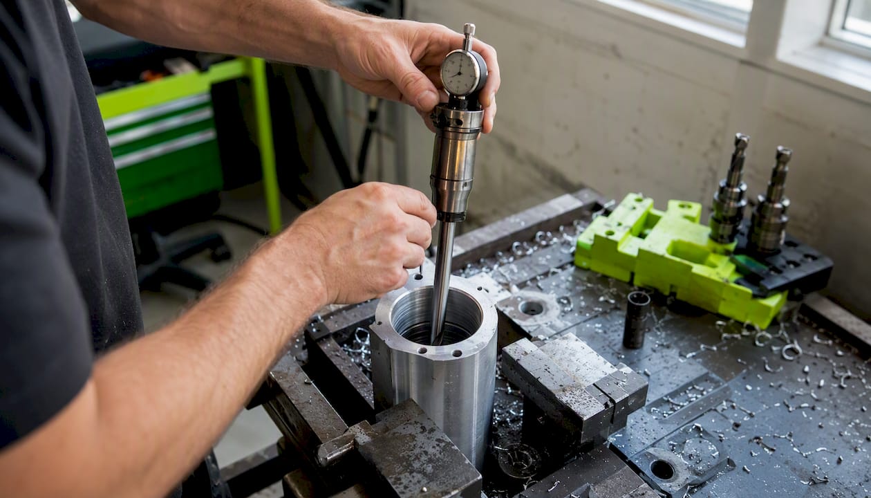
Fixturing stiffness is often the limiting factor on small shops' capability. A part that moves 0.0005" under clamping load between the first and second clamp position will never hold ±0.001" consistently. The number of re-clampings also matters: every time a part comes off the machine and goes back on, it introduces a repositioning error. Five-axis machining reduces re-clamping and is often worth the setup premium for tight multi-face relationships.
Backlash and servo resolution set a hard floor on what a machine can achieve. A machine with 0.001" of backlash cannot reliably hold ±0.0005" without compensation, and even with compensation, the result is less reliable than a machine with tighter mechanical construction.
Inspection capability is part of the process, not an afterthought. The 10:1 rule states that gauge resolution should be roughly ten times better than the part tolerance. For a ±0.001" tolerance, you need a gauge resolving to 0.0001". For extremely tight work, shops may accept a 5:1 or 4:1 ratio, but only after a documented Gauge R&R study confirms the measurement system is adequate.
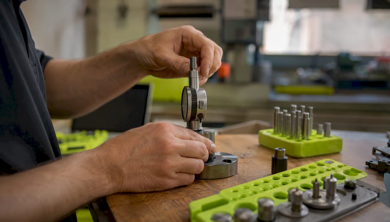
Pro Tip: Before sending a drawing with tight callouts to a new shop, ask for their process capability data (Cpk) on similar features. A shop that cannot produce Cpk data for a feature class probably cannot hold it reliably at volume. Also ask whether they have a CMM and what their warm-up procedure is for the relevant machine.
How to specify tight tolerances correctly on drawings
The drawing is where most tight-tolerance problems start. Ambiguous callouts, missing datums, and over-specified secondary features all create cost and confusion that could have been avoided at the design stage.
ASME Y14.5 is the authoritative standard for GD&T in the United States. It standardizes symbols, rules, and interpretation so that a position callout on your drawing means exactly the same thing to every shop reading it. When tolerances get tight, GD&T is almost always the right choice over ±bilateral dimensions, because GD&T controls the relationship between features, not just their individual sizes.
The core principle: A tight size tolerance on a bore means nothing without a controlled datum. If the bore is positioned relative to a face that is itself uncontrolled, the assembly will still fail. Datum selection is the first decision in tight-tolerance drawing practice, and it should reflect the actual assembly interface, not the most convenient machining reference.
Size-only tolerances (±0.001" on a diameter) are appropriate when fit is the only concern and the feature has no critical relationship to other geometry. Position and profile controls are appropriate when the feature's location, orientation, or form relative to other features matters. For a bearing bore in a housing, you need both: a tight size tolerance for the fit and a position tolerance to keep the bore centered on the shaft axis.
MMC (Maximum Material Condition) and LMC (Least Material Condition) modifiers are worth using when the functional requirement is clearance or interference fit, because they allow the position tolerance to increase as the feature departs from its critical size. This is not a way to loosen tolerances arbitrarily; it is a way to recover tolerance where the geometry allows it, which reduces cost without compromising function.
Surface finish belongs on the drawing whenever the surface has a functional role. For sealing faces, specify Ra (arithmetic mean roughness) or Rz (mean peak-to-valley height) with a functional justification. A tribology study on surface roughness and contact behavior confirms that surface asperities directly influence wear and sealing performance, so a tight dimensional tolerance on a seal groove without a finish callout leaves a critical variable uncontrolled. For anodized or coated parts, coating thickness adds to the finished dimension, so the pre-coat tolerance needs to account for that stack. The hardcoat anodize thickness guide covers how to handle that correctly on CNC drawings.
When do tight tolerances add cost without adding function?
Over-tolerancing is one of the most common and expensive mistakes in precision part design. A blanket ±0.001" title block tolerance on a part with 40 features means the shop must treat every surface as critical, even the ones that only need to look good.
Run this three-question test on every tight callout before releasing a drawing:
- Does this tolerance directly affect fit, function, or assembly? If the answer is no, the tolerance is cosmetic and should be relaxed.
- Is there an alternate control that achieves the same functional result? A profile tolerance on a mating face often replaces three separate size and flatness callouts with one, reducing inspection burden.
- Can this tolerance be measured repeatably at the expected batch size? A ±0.0005" callout on a feature that can only be measured on a CMM is a problem for a 500-piece run where CMM time is the bottleneck.
Cost escalation is not linear. Moving from ±0.005" to ±0.002" adds setup time and may require a different toolpath. Moving from ±0.002" to ±0.001" often requires a different machine or process. Moving below ±0.0005" typically requires grinding or lapping, a separate operation, and a temperature-controlled environment. Each threshold jump multiplies cost, not just adds to it.
Practical rescue options for over-toleranced designs include statistical tolerancing, which allows individual feature tolerances to be relaxed when the assembly's functional requirement is driven by the sum of several features rather than any single one. Limiting tight callouts to the three or four features that actually drive assembly function, and specifying process sequence (grind after heat treat, for example) rather than just a final dimension, are both effective ways to reduce cost without compromising the part's job.
Typical achievable tolerances by process
Process selection is the single biggest lever on what tolerance is achievable. The table below reflects typical production capability for common processes on steel and aluminum; harder materials and complex geometries will push toward the looser end of each range.
Material notes: Titanium and stainless steel work-harden and generate heat, which pushes achievable tolerances toward the looser end of each range without careful tooling and coolant management. Aluminum (particularly 6061-T6 vs T6511) machines cleanly and holds tight tolerances well, but thermal expansion is significant for very tight work. Plastics and composites are the hardest to hold tight: they creep, absorb moisture, and respond poorly to clamping forces.
Process chaining is the standard approach for features that need both tight size and good finish. The typical sequence is: rough machine, semi-finish machine, heat treat (if required), grind or hone to final size. Specifying the process sequence on the drawing, or at minimum noting "grind after heat treat," prevents a shop from trying to hit a final ground dimension in a single milling operation.
How tight tolerances are measured and controlled in production
Planning inspection up front is as important as planning the machining process. A tolerance that cannot be measured reliably cannot be controlled reliably.
- CMM (Coordinate Measuring Machine). The workhorse for tight-tolerance inspection. A CMM measures position, form, and size in three dimensions and generates reports that map directly to GD&T callouts. For first-article inspection on tight-tolerance parts, CMM is almost always required.
- Air gauges. Extremely sensitive for bore diameter measurement, capable of resolving to 0.00005" in production environments. Fast and repeatable, but limited to specific bore sizes and require dedicated tooling per diameter.
- Plug and ring gauges. Go/No-Go gauges are fast and operator-independent for high-volume production. They confirm conformance but do not give variable data. For go/no-go gauge selection and design, the gauge tolerance must be a fraction of the part tolerance, which is where the 10:1 rule applies directly.
- Optical comparators and vision systems. Useful for 2D profiles, thread forms, and features that are difficult to probe mechanically. Wire EDM parts and complex slot profiles often use optical verification.
- High-resolution handheld instruments. Digital micrometers resolving to 0.00005" and electronic bore gauges are practical for in-process checks without pulling a part to the CMM.
First-article inspection (FAI) should be planned as a line item in the quote for any tight-tolerance job. FAI confirms that the process is capable before committing to a full run. For production runs, process capability targets (Cpk ≥ 1.33 is a common minimum for critical features; Cpk ≥ 1.67 for safety-critical applications) should be agreed before the job starts, not after the first batch ships.
Gauge R&R (Repeatability and Reproducibility) studies confirm that the measurement system itself is not consuming a significant fraction of the tolerance. For tight work, measurement uncertainty should be documented and included in the inspection report.
In-process control loops are what separate shops that hold tolerances from shops that inspect their way to conformance. Practical controls include spindle probing after roughing to set tool offsets, SPC alarms that flag drift before parts go out of spec, and automatic tool-length compensation after each tool change.
How tight tolerances change cost and lead time
Tight tolerances affect every line item in a quote. Understanding the cost drivers gives you leverage to reduce spend without compromising function.
- Setup and fixturing cost rises because tight work requires dedicated fixtures, more precise workholding, and longer setup verification. A part that takes 20 minutes to set up at ±0.005" may take 90 minutes at ±0.001".
- Cycle time increases because tight tolerances require slower feeds, lighter cuts, and more passes. Material removal rate drops significantly as tolerances tighten.
- Special tooling may be required: precision boring bars, CBN inserts for hardened steel, or dedicated grinding wheels. These are often amortized across a run but add to the first-article cost.
- Inspection time scales with the number of tight callouts. A CMM program for a 40-feature part with 10 tight callouts takes longer to run and report than one with 3.
- Scrap and rework increase as tolerances tighten, because the process window narrows. A shop running at Cpk 1.0 on a ±0.001" feature will produce more scrap than one running at Cpk 1.67.
Practical cost-reduction tactics:
- Tighten only the three to five features that actually drive assembly function. Leave everything else at ±0.005" or looser.
- Allow more tolerance on secondary geometry (non-mating faces, clearance holes, cosmetic surfaces).
- Choose 5-axis machining for multi-face parts to reduce re-clamping and the associated repositioning error.
- Specify inspection responsibility clearly in the RFQ: which features need CMM, which can use gauges, and what Cpk is required.
- Include critical features, expected Cpk, batch size, and inspection requirements in your RFQ. A shop that receives a complete package quotes more accurately and with less contingency padding.
Worked example: blanket tolerances vs. targeted critical tolerances
A hydraulic manifold block came to the shop with a blanket ±0.001" title block tolerance applied to all 47 features. The part had four functional interfaces: two O-ring port faces, one precision bore for a spool valve, and one mounting face that located the manifold to a pump body.
Before: Every feature on the drawing required CMM verification. Setup time was 3.5 hours per batch. Scrap rate on the first run was roughly one in five parts, driven almost entirely by position failures on non-critical cross-drilled passages that had no assembly function. Lead time was 14 days for a 10-piece run.
After the DFM review: The shop and engineer agreed to tighten only the four functional interfaces: ±0.0005" on the spool bore diameter, a position tolerance of ±0.001" on the spool bore axis relative to the mounting face datum, Ra 32 µin on the O-ring port faces, and ±0.002" flatness on the mounting face. All other features moved to ±0.005". The spool bore was moved to a grinding operation after milling.
The shop's execution checklist:
- Established a primary datum on the mounting face and machined all critical features in a single setup referenced to that datum.
- Added a warm-up cycle of 30 minutes before cutting the spool bore.
- Used in-process probing after the rough bore to set the finish boring bar offset.
- Ground the spool bore to final size in a separate operation with air-gauge verification at each pass.
- Ran CMM on the four critical features only; used go/no-go gauges for the remaining passages.
Result: Setup time dropped to 1.5 hours. Scrap rate on the second run was zero. Lead time came down to 9 days. The part passed first-article inspection on the first attempt.
The lesson is not that tight tolerances are bad. It is that tight tolerances on the wrong features are expensive and provide no functional return. Targeting the four features that actually mattered let the shop focus its capability where it counted.
The tolerance conversation most engineers skip
Most articles on tight tolerance machining focus on what tolerances are achievable. The more useful question is: what tolerance does your part actually need, and are you communicating it in a way a shop can act on?
The worked example above is not unusual. Over-toleranced drawings are the norm, not the exception, in prototype and short-run work. Engineers often apply tight callouts as a defensive measure, reasoning that tighter is safer. It is not. A blanket ±0.001" drawing tells the shop that every surface is equally critical, which means the shop cannot prioritize, cannot optimize its process, and cannot quote accurately. The result is higher cost, longer lead time, and often worse quality on the features that actually matter, because the shop's inspection bandwidth is spread across 47 features instead of four.
The other thing most articles skip is the measurement conversation. A tolerance that cannot be measured is not a tolerance; it is a wish. Before you put ±0.0005" on a drawing, confirm that the shop has a gauge capable of resolving to 0.00005" and that the gauge has been validated for that feature geometry. If it has not, you are not holding ±0.0005"; you are hoping for it.
The best tight-tolerance work happens when the engineer and the machinist talk before the drawing is released, not after the first article fails.
Flying Chip Factory handles tight-tolerance CNC work directly
When you need prototype or short-run parts with genuine tight-tolerance requirements, the difference between a shop that can hold ±0.001" and one that merely quotes it comes down to process planning, measurement capability, and the willingness to have the DFM conversation before cutting starts.

Flying Chip Factory is a CNC job shop in Athens, Alabama, built around direct machinist access. There is no quoting layer between you and the person running the machine. When you send a drawing with tight callouts, the machinist reviews it, flags features that will drive cost without improving function, and confirms measurement capability before the job starts. The shop handles prototypes, short-run production, and fixture work, with experience on tight-tolerance assemblies including bearing fits, sealing interfaces, and precision locating features.
To get a realistic quote, send your drawing with critical features identified, expected Cpk if you have a requirement, batch size, and any inspection deliverables you need. First-article inspection and CMM reporting are available. Request a quote or manufacturability review and get a response from the machinist, not a sales queue.
Sources
- Dimensioning and Tolerancing2018 | ASME
- Measurement Rules of Thumb, Part 1 | Quality Digest
- What is Considered a Tight Tolerance in Machining? Engineering Standards Explained | Modus Advanced
- Surface finish: function and cost relationship | UTEC Resources