
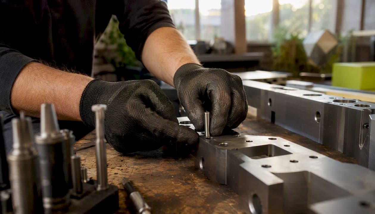
For most alignment applications, call out an H7 hole with an h6 pin for a slip fit, or an H7 hole with a p6 pin for a guaranteed press fit. Those two combinations cover the majority of dowel-pin work you'll put on drawings, and they're what shops expect to see.
A few quick defaults before diving deeper:
- Through-holes, slip fit (H7/h6): Use for re-assemblable fixtures, jigs, and locating features you'll service. Expect a small positive clearance.
- Through-holes, press fit (H7/p6): Use for permanently located parts carrying shear loads. Interference typically runs a small positive amount within a range accepted for most metals.
- Blind holes: Avoid press fits in blind holes when possible. Air entrapment prevents full seating and makes removal destructive.
- Minimum engagement depth: At least 2× the dowel diameter for interference and transition fits.
Reference standards: ISO 286 for metric limits and fits, ASME/ANSI fit tables, and Machinery's Handbook for both systems.
Key Takeaways
Correct dowel-pin hole tolerances start with H7 holes and pin tolerance class selection (h6, m6, or p6) to achieve the required fit without changing the machining process.
| Point | Details |
|---|---|
| Default callout | Use H7 hole with h6 pin for slip fit, or H7 hole with p6 pin for guaranteed press fit. |
| Interference range | Acceptable press-fit interference for most metals runs 0.0005"–0.002"; hole quality must be held to 0.0002"–0.0005" total tolerance. |
| Minimum engagement depth | Interference and transition holes need at least 2× the dowel diameter; add chamfer allowance (0.20–0.40 mm) for blind holes. |
| Avoid blind press fits | Air entrapment in blind holes prevents full seating; prefer through-holes or add a vent when blind holes are unavoidable. |
| Flying Chip Factory | Provides CNC prototype and short-run machining with direct machinist access for tight-tolerance dowel features and quick-turn quoting. |
What do dowel pin hole tolerances look like in a reference table?
The table below covers the most common nominal sizes. Hole and pin tolerance classes follow ISO 286 conventions; imperial sizes are mapped to equivalent fit classes. Copy these callouts directly onto drawings, then verify against your specific material and surface-finish requirements.
Caveats: Values assume ground steel dowels in steel or aluminum bores. Aluminum bores expand more than steel under temperature, which can reduce effective interference at elevated service temperatures. For blind-hole press fits, air entrapment is a real assembly risk. SPIROL's hole-preparation guidance confirms that acceptable press-fit interference for most metals falls between 0.0005" and 0.002", and that consistent performance requires holes held to total tolerances of 0.0002"–0.0005" for straightness, roundness, and finish. Production variance in a typical job-shop ream can consume 30–50% of that total tolerance budget, so check your process capability before tightening the callout further.
For larger dowels (M20 and above), verify worst-case interference carefully. At larger diameters, absolute interference values may be small relative to shear loads, requiring different design approaches.
Spec note: When multiple dowels locate a single assembly, match-machine the holes or tighten positional tolerances on the drawing. Two independently drilled holes rarely align closely enough for a tight press fit in both bores simultaneously.
What's the practical difference between clearance, transition, and interference fits?
The fit family determines what happens when you push the pin into the hole. Getting this wrong means either a pin that falls out or one you can't remove without a press.
Clearance fits (H7/h6, H7/h7) always produce a positive gap between pin and bore. The pin slides in by hand or with light finger pressure. Use these for re-assemblable fixtures, tooling plates, and any locating feature you'll disassemble regularly. The Engineers Edge dowel-pin tolerance table lists slip-fit hole sizes alongside press-fit sizes for common imperial diameters, and the difference in hole diameter is often only a few tenths of a thousandth of an inch.
Transition fits (H7/m6, H7/k6) sit in the middle. Depending on where actual pin and hole dimensions land within their tolerance bands, you might get a light interference or a very small clearance. Assembly typically requires a mallet or a small arbor press. These work well for fixed-location locators that see occasional service, where you want the pin snug but not permanently locked.
Interference fits (H7/p6, H7/r6) guarantee the pin is always larger than the hole. The pin goes in under press force and stays put. Use these for parts carrying shear loads, permanent subassemblies, and anywhere vibration would walk a slip-fit pin out of position.
A few factors shift which class you can realistically hold:
- Material: Aluminum bores close up slightly during reaming due to springback, which can turn a nominal clearance into a light interference.
- Surface finish: A rough bore increases effective friction and can make a transition fit behave like a press fit during assembly.
- Pin type: Ground dowels require tight holes. Knurled, grooved, or spring pins are designed to accommodate looser hole tolerances, which can cut hole-preparation cost significantly when exact location isn't critical.
NK Labs' pinned-joint layout guidance makes a point worth internalizing: use one round press-fit locator and make the second hole a slot or diamond shape. Two round press-fit holes over-constrain the assembly and make it nearly impossible to assemble if center-to-center spacing is off by even a fraction.
How do you choose the right dowel-hole tolerance for your part?
Start with function, then work backward to the tolerance class.
Alignment only, no shear load: H7/h6 slip fit. Easy to assemble, easy to service, and any competent shop can hold H7 with a standard reamer.
Shear load, permanent assembly: H7/p6 press fit. The pin carries the load mechanically, not through friction alone.
Repeated service, moderate load: H7/m6 transition. Snug enough to stay located, loose enough to remove with a press rather than a torch.
Environmental factors matter too. If the assembly sees wide temperature swings, an aluminum housing with a steel pin will lose interference as temperature rises. Size the interference at the cold end of the operating range, not at room temperature.
On the manufacturing side, H7 is the sweet spot. Shops drill undersize and ream to H7 as a standard workflow. Specifying H6 or tighter requires jig boring or honing, which adds setup time and cost. As practitioners on Eng-Tips note, the smarter move is to hold the hole to H7 and select the pin tolerance class (h6, m6, or p6) to get the fit you need. Changing the pin class is cheap. Changing the hole class is not.
Pro Tip: Specify the hole tolerance class on the drawing (e.g., "Ø8 H7") and call out the pin class separately. Never write "press fit" without a tolerance class. "Press fit" means different things to different machinists, and you'll get inconsistent results across shops.
For assemblies with multiple dowels, either match-machine the holes in the assembled stack or use a slot on the second locator. Two independently located round holes almost always require some forcing during assembly, which damages bores and defeats the purpose of tight tolerances.
Hole depth, chamfer, and installation best practices
Engagement length is where a lot of designs go wrong. A short hole gives the pin almost no bearing surface, and under shear load the bore walls deform.
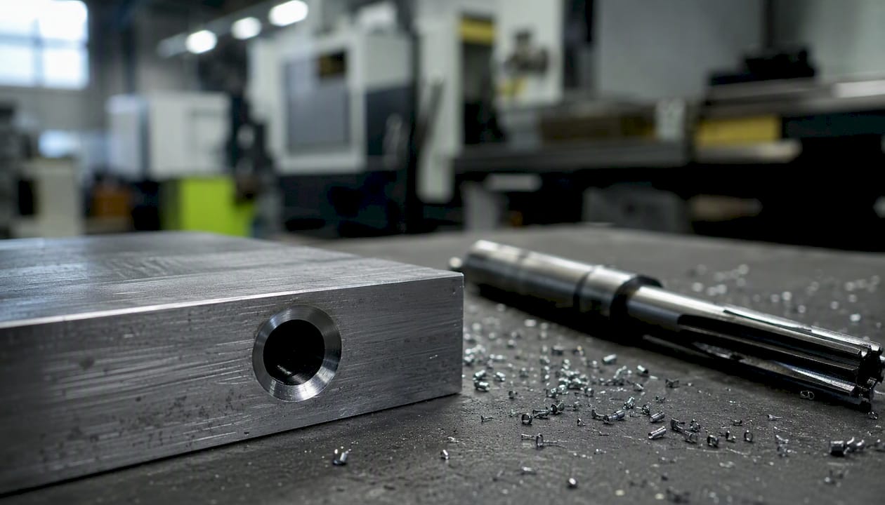
Factorem's dowel-pin guidance sets the minimum engagement depth at 2× the dowel diameter for interference and transition fits. That's the floor. For high shear loads or soft materials like aluminum, 2.5×D is a safer target.
Chamfer sizing: Entry chamfers on the hole reduce galling during press-fit installation. For metric holes, a 0.20–0.40 mm chamfer at 45° works for diameters under 12 mm. Larger diameters (12 mm and up) benefit from a 0.40–0.60 mm chamfer. The chamfer depth counts against your engagement length, so add it to the total hole depth on the drawing.
Blind holes: Avoid press-fitting into blind holes. Air trapped below the pin creates back-pressure that prevents full seating, and the pin looks seated when it isn't. If a blind hole is unavoidable, add a small vent hole at the bottom or specify a vented pin. Design the hole depth to accommodate the full pin length plus the chamfer allowance, with at least 0.5 mm of clearance below the pin tip.
Pro Tip: Press the pin into the more durable, non-wearing member first. Use a slip fit in the replaceable member so field replacement doesn't damage the base bore. Document the replacement pin tolerance in your maintenance notes.
Installation best practices:
- Mark assembly orientation on the drawing when pin location is asymmetric.
- Use a pin press or arbor press, not a hammer, for interference fits. Hammering cocks the pin and damages the bore entry.
- For aluminum parts, a light coat of anti-seize on the pin shank reduces galling during press-in without meaningfully affecting the interference.
How shops machine and inspect dowel holes to meet spec
The standard workflow for an H7 hole is straightforward: drill to 0.010"–0.015" undersize, then ream to finish diameter. A sharp, properly sized chucking reamer in a rigid setup will hold H7 in steel and aluminum reliably. Jig boring or honing is reserved for H6 and tighter, or for materials that don't ream cleanly.
Surface finish matters as much as diameter. SPIROL's hole-preparation data shows that holes need to be held to total tolerances of 0.0002"–0.0005" for straightness and roundness to get consistent press-fit performance. A reamed hole that's slightly bell-mouthed at the entry will give inconsistent insertion force and can allow the pin to rock under load.
Inspection workflow:
- Measure pin OD with a micrometer before installation. Ground dowels from reputable suppliers hold h6 reliably, but verify on critical assemblies.
- Measure hole ID with a bore gauge or plug gauge. Calipers are not accurate enough for H7 tolerances on small diameters.
- Use go/no-go gauges for production runs. A go gauge confirms the hole is large enough; a no-go gauge confirms it hasn't been reamed oversize.
- For short-run prototype work, a calibrated bore gauge and a micrometer are sufficient. For production, go/no-go gauges are faster and less operator-dependent.
Pro Tip: When reaming aluminum, use a reamer sized 0.0002"–0.0003" smaller than the nominal H7 upper limit. Aluminum springs back slightly after the reamer passes, and a standard H7 reamer often produces a hole at the high end of the tolerance band in soft alloys.
When exact location isn't critical and budget is tight, knurled or spring pins are worth considering. They're designed for looser hole tolerances and eliminate the reaming step entirely.
What standards and handbooks should you consult?
The short list:
- ISO 286-1 and ISO 286-2: Define the fundamental deviation and tolerance grade system (H7, h6, p6, etc.) for metric fits. This is the primary reference for metric dowel tolerances.
- ASME B4.1 and B4.2: Cover preferred limits and fits for inch and metric sizes respectively. ASME Y14.5 governs how tolerances are called out on drawings.
- Machinery's Handbook: Tables 8 and 9 (in recent editions) give clearance, transition, and interference fit limits for both inch and metric systems. The most dog-eared reference in most shops.
- JIS B 0401: The Japanese Industrial Standard for limits and fits. Misumi's JIS excerpts are a convenient free reference for metric tolerance ranges.
- DIN 7 / EN ISO 8734: Define standard dowel-pin dimensions and tolerances for metric ground pins (m6 tolerance class is common for DIN 7 pins).
Drawing callout examples:
- Metric slip fit:
Ø8 H7 / h6(hole H7, pin h6) - Metric press fit:
Ø8 H7 / p6(hole H7, pin p6) - Imperial press fit:
Ø.250 +.0000/−.0005(hole), pin to ASME B18.8.2
For metric work, ISO 286 is the cleaner system. For inch work in the US, ASME B4.1 is the governing document, though many shops are comfortable with ISO fits on metric drawings. When mixing systems on a drawing, call out the standard explicitly.
How Flying Chip Factory applies these tolerances in production
When a drawing comes in with a dowel-pin callout, the first thing we check is whether the hole tolerance class is explicitly stated. "Press fit" with no tolerance class is the single most common source of rework on tolerance-critical jobs. We'll always ask for a clarification before cutting metal.
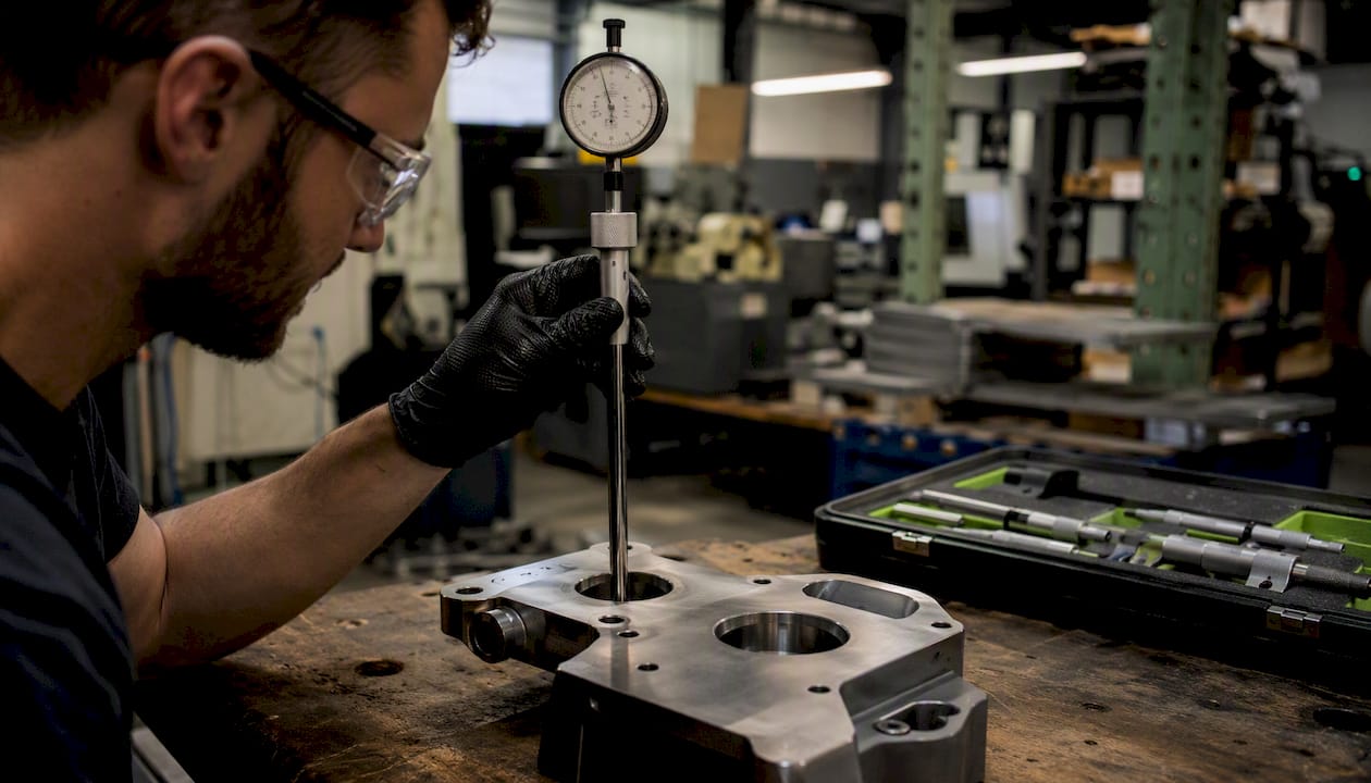
For prototype work, our typical workflow is drill plus ream for H7 holes, with bore gauge verification before the part leaves the machine. For production runs, we set up go/no-go gauges after the first article inspection. When a designer specifies H6 or tighter, we flag it during quoting because it changes the process from a standard ream to a jig-bore or hone, and that affects both lead time and price.
Match-machining is something we recommend when a customer brings in a multi-dowel assembly and the mating parts aren't being made in the same run. Two parts drilled independently to ±0.001" positional tolerance on the hole centers will fight each other during assembly. Machining both halves together, or at minimum using a common fixture, eliminates that problem.
Pro Tip: If you're designing a fixture or tooling plate with multiple dowels, call out the hole locations with true position tolerances (per ASME Y14.5) rather than coordinate tolerances. It gives the shop a cleaner target and makes inspection straightforward.
We also machine our own motorcycle parts to tight tolerances, so we're not just running customer jobs. That production experience informs how we quote and how we communicate about tolerance tradeoffs. If you have a part with tight dowel-pin requirements, reach out for a quote and we'll tell you exactly what's achievable and at what cost.
What the tolerance spec doesn't tell you
Most tolerance guides stop at the numbers. The part that actually causes assembly failures is the gap between what the drawing says and what the machinist understands.
"Press fit" written on a drawing without a tolerance class is an instruction to guess. One machinist reads it as H7/p6. Another reads it as "tight." A third calls the engineer. The third machinist is the one you want, but you can't count on getting them every time. An explicit tolerance class costs you nothing on the drawing and saves real money in the shop.
The other thing worth saying: for most prototype and short-run work, H7/h6 and H7/p6 cover 90% of what you'll encounter. The exotic tolerance classes exist for a reason, but chasing H6 holes on a prototype fixture is usually a waste of setup time. Get the fit family right, hold H7, and select the pin class to dial in the interference. That's the approach that produces repeatable results across shops without inflating cost.
Flying Chip Factory machines tight-tolerance dowel features on real production parts
Specifying correct dowel pin hole tolerances is only half the job. The other half is finding a shop that can hold them without a three-week lead time and a phone tag marathon.

Flying Chip Factory is a CNC job shop in Athens, Alabama, with direct machinist access from day one. No account managers, no relay chain. You talk to the person running the machine, which means tolerance questions get answered in hours, not days. The shop handles prototype machining, short-run production, and fixture work, and the same processes used to hold tight tolerances on in-house motorcycle parts are applied to every customer job. If your drawing calls out H7/p6 on a 6 mm dowel bore, we know exactly what that means and how to verify it.
Request a quote for your next tolerance-critical part and get a real answer on what's achievable and what it costs.
Sources
- Hole Preparation for Press Fit Pins | SPIROL
- Dowel Pin Installation Design Tolerance Table Chart
- Tolerance for Dowel Holes
- Dowel Pin Hole Sizing