
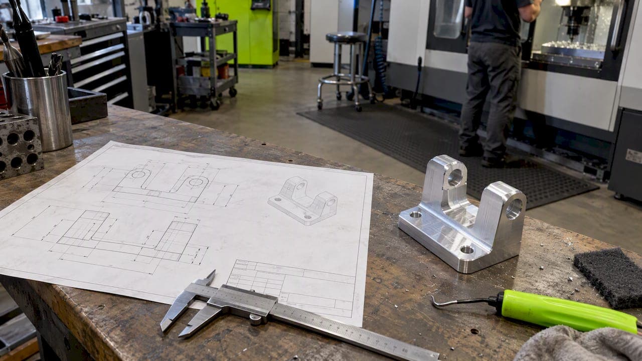
A CNC drawing standard is the agreed set of rules for how a part is shown, dimensioned, toleranced and revised, so the person cutting metal reads it the way the designer meant it. In the US that usually means ASME Y14.5 for dimensioning and tolerancing, ASME Y14.100 for general drawing practice, third-angle projection, and a title block that carries part number, revision, material and units. Get those right and a machine shop can quote and cut without a string of questions.
This guide walks through what a shop expects to see, how to handle revisions, and a checklist you can run before you hit send.
TL;DR
- Send a 2D PDF drawing and a 3D STEP file together. The drawing carries tolerances, finishes and material. The model drives the toolpaths.
- Name your standard on the print. In the US that is typically ASME Y14.5-2018 with third-angle projection and a complete title block.
- Call out only the tolerances that matter. Put a general tolerance in the title block and tighten individual features that have a function.
- Control revisions with letters, a change log and one source of truth, so nobody machines to a superseded print.
- Run the checklist below before sending. Missing information is what slows most quotes.
Why drawings still matter when you have a CAD model
It is tempting to send a model and assume the shop will figure it out. A solid model describes shape. It does not say which surface is a bearing bore, which face seals against an O-ring, what finish a bracket needs or what alloy and temper the part is made from.
NIST research on tying design to machining makes the point from the machine side: a significant amount of information is lost when a CAD model is reduced to G-code, and richer formats such as STEP-NC (ISO 14649) are being developed to close that gap. Until they are common in everyday shops, the drawing remains the document that carries tolerances, surface finish and fit requirements.
That is why most shops ask for both files. The 2D drawing is the reference for what the part must be. The 3D file saves the programmer from retyping geometry. If you are unsure which model format to send, our note on sending STEP instead of STL explains why a neutral solid format avoids a round of questions.

The standards behind a CNC drawing
There is no single "CNC drawing standard." A good print draws on a small family of them.
ASME Y14.5 for dimensioning and tolerancing
ASME Y14.5-2018 is the US standard for geometric dimensioning and tolerancing (GD&T). It defines the symbols, rules and definitions used to communicate design intent so a part achieves its intended form, fit and function. ASME lists the 2018 edition, reaffirmed in 2024, as current and in effect, on stabilized maintenance until a new revision is approved.
The practical value is that GD&T states how a part must function rather than leaving a machinist to interpret a picture. When a position or perpendicularity callout is unambiguous, the shop can choose the most efficient way to make and inspect the feature. If you are new to the symbols, start with datums, since every other callout depends on them. Our piece on three checks for GD&T datums covers the usual assembly failures.
ASME Y14.100 for general drawing practice
Y14.5 tells you how to tolerance. ASME Y14.100 establishes the essential requirements for preparing and revising engineering drawings and their associated lists, and it is meant to be used alongside other Y14 standards. The version listed on that page is a historical 2013 edition that was revised by a 2017 edition, so check which edition your company or customer cites before you write it on a print.
ISO as the alternative system
Many shops outside the US, and plenty of US shops with international customers, work to ISO geometrical product specifications and use ISO general tolerances. Either system works as long as everyone reads it the same way. What fails is a print that mixes them or never says which one applies. Put the governing standard in the title block or a general note.
What belongs on a CNC drawing
Here is the minimum a machinist expects, based on the drawing checklists and shop standards we reviewed, with the University of Central Florida's published machine lab drafting standards as a useful real-world example of how a shop writes its expectations down.
| Element | What to include | Why it matters |
|---|---|---|
| Title block | Part name, part number, revision, material, quantity, drawn by, date | Identifies the exact part and version being quoted |
| Units | Inch or millimeter, stated once and clearly | Prevents a 25.4x error |
| Projection | Third-angle in the US, with the symbol | Views get read in the right arrangement |
| Dimensions | Fully defined, no duplicates, no guessing from the model | The shop should never scale a drawing |
| Tolerances | General block plus tighter callouts on functional features | Controls cost and fit |
| Threads | Size, pitch, class, depth, and whether it is a through or blind hole | Determines tap or thread mill selection |
| Holes | Diameter, depth, counterbore or countersink, and tolerance if it is a fit | Drives tooling and inspection |
| Surface finish | Roughness value on functional faces only | Finish adds machining time |
| Secondary processes | Anodize, heat treat, plating, with the spec | Affects dimensions and lead time |
| Material | Alloy and temper or grade, not just "aluminum" | Changes machinability and strength |
A few of these deserve more explanation.
Projection and software defaults
The University of Central Florida shop standards warn that CAD software defaults are often wrong or mismatched with a shop's preferences, so you need to confirm the projection angle and dimensioning standard (for example ANSI) when you export. Build a template once with your title block, third-angle projection and units, then start every new drawing from it. That one habit removes a whole category of inconsistencies.
Materials and finishes
Write the full designation. "Aluminum" leaves the shop choosing between alloys with very different cost and behavior. If a part is anodized, say whether the coating thickness is part of the dimension or added on top. Anodizing is a classic place where drawings go quiet, and our hardcoat anodize thickness guide shows how to specify it so finished dimensions land where you want them.
Threads
Name the thread system, not just a nominal size. Pipe threads in particular are easy to confuse, and the mistake is expensive. Our comparison of NPT and BSP threads shows the callout details that prevent it.
Tolerances: tight where it works, loose everywhere else
The fastest way to raise the price of a part is to put a tight tolerance on every dimension. The fastest way to get a bad part is to leave a critical dimension on a loose general tolerance.
The approach that works:
- Set a sensible general tolerance in the title block that covers every dimension you did not call out.
- Identify the features that actually control function: bearing seats, sealing faces, locating holes, mating surfaces.
- Tighten only those, and say exactly how the feature will be measured through its datum reference.
- Leave cosmetic and clearance features alone.
NIST-linked guidance used across the industry stresses the same thing: never assume a machinist will infer how a bearing fit or sealing surface should be handled from geometry alone. State the tolerance, the material and the roughness on the print.
For a starting point on typical values and how they tie to ISO 2768, see this reference on CNC tolerances tied to ISO 2768. If your part really does need tight limits, read our practical guide to tight tolerance machining before you commit, because inspection method and temperature stability start to matter as much as the machine.
Position and perpendicularity
Two callouts cause the most confusion. True position replaces coordinate tolerance boxes around holes with a circular zone, which usually gives the shop more usable tolerance; see our true position basics. Perpendicularity needs a clear datum and a tolerance zone; our perpendicularity callout guide walks through it with NIST-backed examples.
Revision control: keep everyone on the same print
A beautiful drawing is worthless if the shop is cutting from last month's version. Revision control is the discipline of managing, documenting and tracking versions so superseded files never reach the machine.
The habits that hold up in practice:
- One source of truth. Store the released drawing and model in a single place. Email attachments multiply and drift.
- Clear revision labels. Use letters (A, B, C) or numbers (1.0, 1.1) and put the current one in the title block and the file name.
- A change log. Record what changed, who changed it and why. A short revision table on the drawing itself is the standard place for it.
- Revise the model and drawing together. A new STEP file under an old PDF is how mismatches happen.
- Confirm receipt. When you send a new revision to a shop, say which revision it replaces and ask them to confirm they are working from it.
For prototypes you will iterate quickly, so the log matters more, not less. If you want fast turns without losing track, see how rapid CNC prototyping works when the engineer and the machinist talk directly.
A pre-send CNC drawing checklist
Run through this before every request for quote.
- Title block complete: part name, number, revision, material, quantity.
- Units stated and consistent.
- Third-angle projection symbol present (for US shops).
- Governing standard named (ASME Y14.5-2018 or an ISO equivalent).
- Every feature fully dimensioned; no dimension taken from the model.
- General tolerance set; critical tolerances called out only where needed.
- Datums defined and logical for how the part will be fixtured and inspected.
- Threads specified with size, pitch, class and depth.
- Holes specified with depth and type.
- Surface finish noted on functional faces.
- Material alloy and temper, plus any secondary process and its spec.
- PDF and STEP files match, and the revision letter is the same on both.
The cnc-nice style checklists many shops pass around point to the same cause of delay: missing information is the primary reason quotes stall. A print that passes a list like this gets into production faster.
What if you have a part but no drawing?
Sometimes the part exists and the print does not, such as a worn bracket or an out-of-production fitting. You can still get a usable drawing by measuring the functional features, deciding which surfaces mate with what, and writing down intent rather than copying every measured wobble. We cover the process in our guide to reverse engineering without drawings.
Our perspective: what we see at the machine
We design and machine parts in a single shop in Athens, Alabama, and the person who answers your questions is the machinist who will cut the part. That changes how we think about drawings.
The prints that go smoothly are not the most elaborate ones. They are the ones where the designer decided what the part must do and said so plainly. A clean title block, one clear datum scheme and three well-chosen tolerances beat a page of callouts nobody can inspect.

We also build our own products, including a bolt-on kickstand for electric mini dirt bikes, so we sit on both sides of the print. When we draw a part for ourselves, we ask what has to fit, what has to survive, and what can be left alone. When we receive a customer print, we ask the same questions, and a conversation about intent usually saves a revision cycle.
Our advice: if a tolerance has no reason behind it, loosen it. If a feature has a reason, write the reason into a note. And when in doubt, call the machinist before you release the drawing, not after the first part is scrap.
— Drake
Need a part cut from your drawing?
If you have a print and a STEP file ready, we machine prototypes, short production runs, fixtures, brackets and support parts, with direct access to the machinist for quick iteration. Send your files through the Flying Chip Factory site and we will talk through the tolerances before cutting.
If you ride an electric mini bike, our E2 Kickstand for the KTM SX-E 2, GASGAS MC-E 2 and Husqvarna EE 2 is a CNC-machined, bolt-on example of a part drawn and made in-house, priced at $100-$105.
FAQ
What are engineering drawing standards?
They are published rules for how drawings show geometry, dimensions, tolerances, notes and revisions. In the US the main ones are ASME Y14.5 for dimensioning and tolerancing and ASME Y14.100 for general drawing practice. They exist so the designer, the machinist and the inspector all read a print the same way.
Do I still need a drawing if I send a STEP file?
Yes, in most cases. The STEP file defines shape, but it does not reliably carry tolerances, finishes, material grade or thread callouts. Send both, and make sure they carry the same revision.
Should I use first-angle or third-angle projection?
Third-angle is the US convention, and the ASME-based practice most American shops expect. Many other countries use first-angle. Mark the projection symbol on the drawing so nobody has to guess, especially if the print crosses borders.
How do I handle drawing revisions with a machine shop?
Update the revision letter in the title block, log what changed and why, and send the drawing and model together. Tell the shop which revision it replaces and ask for confirmation. Keep a single master copy on your side.
How tight should my general tolerance be?
Tight enough to be safe for non-critical features and loose enough not to inflate cost. Set it in the title block, then tighten only the features that control fit or function. If you are unsure, ask the machinist what the process holds comfortably.
Sources
- ASME Y14.5-2018 Dimensioning and Tolerancing
- ASME Y14.100 Engineering Drawing Practices, ANSI Webstore
- NIST: Tying Together Design, Process Planning and Machining with STEP
- UCF Machine Lab Drafting Standards
- CNC tolerances tied to ISO 2768