

Send STEP for anything that touches a machine tool, and reserve STL or 3MF for the mesh a printer actually slices. STEP carries exact boundary representation geometry, units, and design intent; STL is a triangulated approximation with none of that. Converting a STEP file down to STL is easy and one-way. Going the other direction means rebuilding the part from scratch, so keep the STEP file as your permanent source of truth.
TL;DR:
- Sending a STEP file ensures accurate toolpath generation and reduces the need for geometry reconstruction, which significantly speeds up quoting and machining.
- STEP files store exact boundary geometry, units, and product intent, making them the preferred format for precise manufacturing and inspection processes.
- Converting an STL to STEP is unreliable because it involves reverse engineering approximate mesh data into a parametric CAD model, often resulting in inaccuracies.
- For 3D printing, STL or 3MF files are sufficient, but 3MF better preserves units, materials, and color information, preventing size and print errors.
- Providing critical dimensions and surface finish notes alongside your STEP file enhances quote accuracy and minimizes misunderstandings during production.
STL vs STEP File Differences: What Each Format Actually Stores
STL and STEP solve two different problems, and that's the whole reason the confusion exists. STL stores a triangulated shell: a pile of flat triangles approximating a surface, with no notion of a hole, a fillet, or a wall thickness. There's no unit tag on an STL file, no feature history, and no way to tell if a "circle" is actually 200 tiny straight segments pretending to be round.
STEP is different at the data level, not just the file extension. It's built on boundary representation, or B-Rep, where the model stores actual faces, edges, and mathematically exact surfaces, plus units and assembly structure. The official standard behind it is ISO 10303, commonly just called STEP, and it's why the format survives across SolidWorks, Fusion 360, NX, and Creo without losing dimensional accuracy.
The practical fallout:
- STL: fast to generate, easy for any printer to slice, but purely approximate.
- STEP: exact geometry, native units, editable features and assemblies.
- Chordal deviation (the tessellation setting) determines how closely an STL's triangles hug the real surface. Tighter deviation means smoother curves and a bigger file.
- A high-resolution STL can look identical to a STEP model on screen, but it's still not parametric and cannot be measured with the same precision a CAD engine gives a B-Rep model.
Why Machine Shops Almost Always Ask for STEP
CAM software builds toolpaths from geometry, and the type of geometry it gets changes the quality of the cut. Feed a CAM system a STEP file and it can recognize actual features: a pocket, a bore, a fillet radius, then generate toolpaths that follow the true mathematical surface.
Hand it an STL instead, and the CAM software can only follow the facets it was given. On a curved surface, that produces a toolpath that steps across flat triangle edges rather than a smooth arc, and it can leave visible witness marks on the finished part, especially on anything with cosmetic or sealing surfaces.
Inspection suffers the same way. A STEP file can carry PMI (product manufacturing information), meaning tolerances and finish callouts travel with the geometry. That lets a CMM program run against the exact nominal surface instead of a guess. When shops receive STEP or native CAD files instead of a bare mesh, they skip a step most engineers never see: reconstructing intent.
- Rebuilding a hole's true diameter from an STL's faceted approximation.
- Guessing wall thickness because the mesh has no dimension data behind it.
- Sending an RFI back to the customer, which adds a day or two to quoting before a single chip flies.
Pro Tip: If a shop asks why they want STEP instead of the STL you already have, it's rarely pickiness. It's the difference between a same-day quote and a week of back-and-forth clarifying what a curve was actually supposed to do.
Best File Format for 3D Printing and Slicer Workflows
Every slicer eventually needs a mesh, full stop. That's true even for slicers that now accept STEP directly. Under the hood, they convert that STEP geometry into triangles before generating a single layer, so the mesh step never actually goes away, it just happens automatically instead of manually.
What you control is the mesh's resolution. Chordal deviation between 0.01 and 0.05 mm is a reasonable range for FDM, and going finer than that rarely improves the printed result on a standard nozzle. Resin printers reward tighter tessellation because layer heights are smaller and surface detail shows up more.
- STL carries no unit metadata, so a model exported in inches can silently import as millimeters. That mistake shrinks a part to roughly 4% of its intended size, and it happens more often than most people expect.
- 3MF avoids that trap by storing units, color, materials, and multiple objects in one container, which is why it's worth using over STL whenever your printer and slicer both support it.
- If you're only sending a part to be printed, not machined, STL or 3MF is genuinely fine. Don't force STEP where a mesh does the job
Why Converting STL to STEP Rarely Works Cleanly
Going from STEP to STL is a one-way trip, and that's by design. The software discards curve equations and replaces them with triangles in a process that's deterministic and repeatable, but nothing comes back the other way for free.
Converting STL to STEP is a different animal entirely. There's no feature history to recover, so software has to guess at surfaces through a process closer to reverse engineering than file conversion. Automated surface recognition tools exist, but they routinely produce messy, over-segmented results on anything more complex than a simple prismatic block.
- If you only have an STL and need real CAD data, rebuild the critical features in your CAD software rather than trying to patch the mesh. Recreating a bore, a boss, or a mating surface directly from measurements is faster and more accurate than coaxing a mesh into a solid.
- Use a 3D scan to CAD workflow when the geometry is organic or you have no original model at all.
- If a vendor asks for STEP and you only have a mesh, tell them why, and hand over the critical dimensions, surface finish requirements, and tolerances separately so the shop isn't guessing blind.
Export and File Handoff Checklist for CNC Quotes
Getting a fast, accurate quote comes down to what you hand the shop, not how good the part looks on your screen. Following a short sequence before you hit send saves real time on both ends.
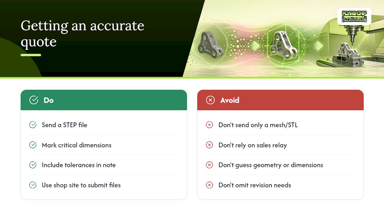
- Keep the STEP file as your master record, and export an STL or 3MF only for whoever specifically needs a mesh.
- Confirm units in writing, especially on anything crossing between inch and metric software.
- Set chordal deviation to match the process. Tight tolerances or CMM inspection call for finer tessellation than a quick visual print.
- Add a short note covering part name, surface finish, hole tolerances, and how the part fits into a larger assembly.
- Where the geometry allows it, annotate the STEP file with PMI or simple callouts on the dimensions that actually matter for function, not just for looks.
Pro Tip: A one-paragraph note with your critical dimensions and finish requirements attached to a STEP file does more for quote accuracy than any amount of extra mesh resolution ever will. Shops with tight tolerance machining experience read that context once and build the CAM program around it instead of emailing you three questions first.
What Sending STEP Actually Saves You at the Shop
Flying Chip Factory runs prototype and short-run jobs the same way most serious shops do: STEP in, CAM features generated straight from the geometry, a quote back, then the part gets machined. That's a fundamentally different workflow than what happens when only an STL shows up.
An STL means someone on the shop side has to reconstruct wall thickness, hole callouts, and finish expectations before a toolpath is even possible. That's time spent on interpretation, not machining, and it usually shows up as a slower quote or a round of emails asking what a certain feature was supposed to do.
Sending STEP up front, ideally with a note on the dimensions and finish that actually matter, tends to mean fewer surprises and a quote that holds up once the part is actually cut.
— Drake
How Flying Chip Factory Handles Prototype and Short-Run Machining
Flying Chip Factory is the alternative to guessing your way through a machine shop's back-and-forth: send a STEP file with the critical dimensions noted, and you get a quote built on the actual geometry instead of a shop's best interpretation of your mesh.

The shop runs prototype machining, short-run production, as well as fixtures, brackets, and support parts, all designed and machined from a single location with direct access to the machinist handling your job. There's no account manager relay and no sales layer between your questions and the person actually running the mill. If your project involves iterating on a design across a few revisions, that direct line matters more than most engineers expect going in, especially when a dimension needs to change mid-run.
The same shop also builds and sells its own line of CNC-machined motorcycle parts, including the E2 Kickstand for the KTM SX-E 2, GASGAS MC-E 2, and Husqvarna EE 2. If you've got a prototype ready to quote, send the STEP file and a quick note on tolerances through Flying Chip Factory's site to get the process started.
Sources
For deeper technical grounding, the STEP vs STL breakdown from CADAGEN covers B-Rep versus mesh geometry in detail. OmniView3D's format comparison explains toolpath and tessellation effects, while TextoCAD's guide covers 3MF and conversion limitations. PartzPro's manufacturing piece ties format choice directly to cost and quoting accuracy.
- STEP vs STL: Which File Do You Actually Need? · CADAGEN
- STL vs STEP: Difference and Which Format to Choose
- STL Files Explained: STL vs STEP vs 3MF for 3D Printing | TextoCAD
- STL vs. STEP: Choosing the right format for CNC machining and 3D printing | PartzPro
FAQ
Is a STEP file better than STL for machining?
Yes, for machining specifically. STEP preserves exact geometry, units, and tolerances that CAM software and CMM inspection need, while STL only offers an approximate mesh.
Is it possible to convert STL to STEP?
Technically yes, but it requires reverse engineering through surface recognition rather than a clean file conversion, and the result rarely matches the original design intent. Rebuilding critical features manually in CAD is usually faster and more reliable.
Is STL the same as STEP?
No. STL stores a triangulated mesh with no units or feature history, while STEP stores exact boundary representation geometry under the ISO 10303 standard, including units and assembly structure.
Can ChatGPT actually make STL files?
Some AI tools can generate basic mesh geometry or script simple shapes into STL format, but they can't produce the parametric, tolerance-accurate geometry a machine shop needs for real production parts. For anything going to a mill, a proper CAD model exported as STEP remains the reliable path.
Does Flying Chip Factory accept STEP files for quotes?
Yes. Flying Chip Factory works from STEP files for prototype machining and short-run production jobs, which lets the shop quote directly from your actual geometry instead of reconstructing it from a mesh.