
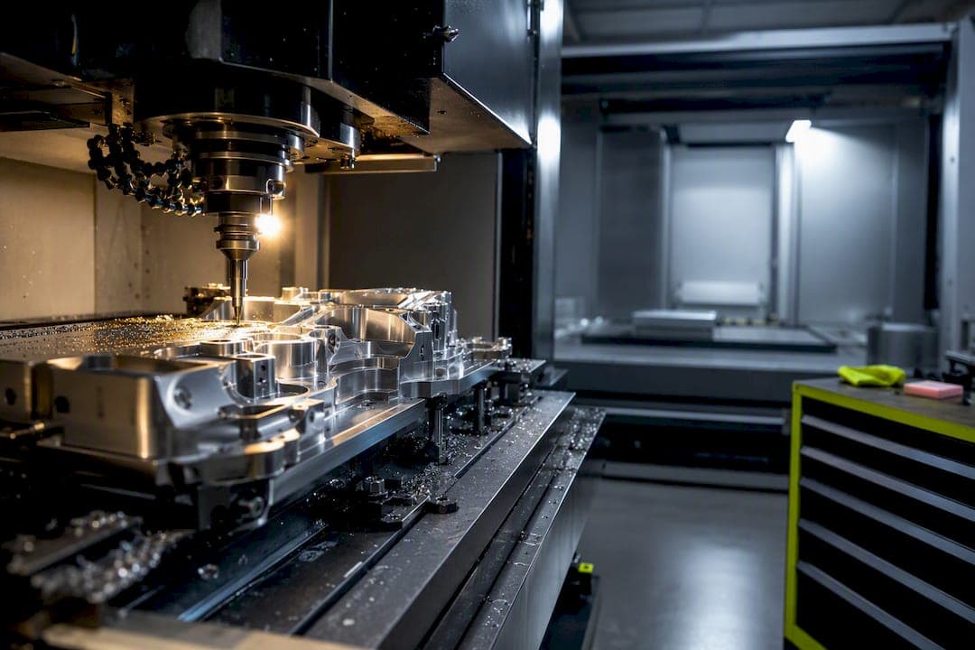
Rapid CNC prototyping produces production-representative parts in days, not weeks, when you supply a complete STEP file and 2D drawing up front. Simple aluminum parts can ship in 2 to 3 business days; more complex geometry with multiple setups typically runs 5 to 10 business days. Pick CNC over additive methods whenever the part needs to behave like its final production counterpart under load, heat, or repeated cycling.
TL;DR:
- Rapid CNC prototypes made from production-grade materials can be delivered in as little as 2 to 3 days for simple aluminum parts, with more complex geometries taking up to 10 days.
- CNC machining provides parts with tight tolerances and smooth finishes that better simulate final production parts, enabling more accurate mechanical and stress testing.
- A complete, detailed file package—including STEP files, dimensioned drawings, and critical tolerances—significantly reduces quoting and setup delays.
- Prioritizing the three most functional features with tight tolerances on your drawings can cut lead times and costs by avoiding unnecessary fixturing and inspection.
- For parts where material properties, load-bearing capacity, or precise mating are critical, CNC is the preferred method over additive manufacturing.
What Is Rapid CNC Prototyping and When Should You Use It?
Rapid CNC prototyping is subtractive machining, milling and turning, applied to prototype quantities with compressed lead times and direct machinist involvement instead of the layered scheduling of a production run. The part comes out of the same block of aluminum, steel, or engineering plastic that your production run will use, cut on the same three or five-axis equipment.
That distinction matters more than most people realize. A 3D-printed nylon bracket can look identical to a machined 6061 bracket and still fail a bolt-preload test the machined version passes easily, because layer-based additive parts and cut production stock behave differently under load. If your prototype exists to answer "will this part survive real use," CNC is usually the faster answer to the right question, even if it isn't the faster process on paper.
Use rapid CNC prototyping when you need a part that mates with existing hardware, withstands mechanical stress, or has to pass an inspection standard before tooling investment. Skip it, at least for the first iteration, when your only checking overall form or aesthetic proportions and additive printing can answer that cheaper.
Why Use CNC for Rapid Prototyping?
The core value of a machined prototype is that it stops being a guess. It's a production-representative part you can torque, load, and cycle exactly like the final product.
Material realism drives most of that confidence. A prototype cut from the actual production alloy, whether that's 6061-T6 aluminum or 304 stainless, carries the same yield strength, thermal expansion, and fatigue behavior as the parts that ship later. CNC machining also holds tighter tolerances and delivers smoother finishes than common additive methods, which is why it's the preferred choice for mechanical testing and fit verification rather than a quick visual check.
That precision supports several specific jobs a rendering or a printed model can't handle:
- Functional testing under real load, torque, or thermal cycling
- Fatigue and durability testing on parts that see repeated stress
- Mating and assembly verification against existing hardware or fasteners
- Bridge production, shipping small quantities of real parts while injection tooling or die casting gets built
The trade-off is cost and material waste. Subtractive machining removes material rather than adding it, so a dense part with deep pockets burns more stock and more spindle time than an additive equivalent. For a prototype meant to prove function, that cost is the price of a real answer instead of an approximate one.
Rapid CNC Prototyping Process: From File to First Part
The cnc prototyping process runs through a predictable sequence, and knowing where delays actually happen helps you plan around them rather than get surprised by them.
- File intake and quoting. A complete package includes a STEP file, a dimensioned 2D drawing with datums and critical tolerances, and a material spec. That completeness is not a formality. Incomplete files are the single biggest cause of quoting delays, because the shop has to stop and ask questions instead of starting to program.
- DFM review. A machinist reviews the drawing for tool access, wall thickness, and tolerance conflicts before committing to a fixture plan. Common flags include deep narrow pockets, sharp internal corners that need a fillet, and tolerances called out on features that don't affect function.
- CAM programming and toolpaths. The shop builds toolpaths around the material, the machine's spindle capability, and the tolerances you've marked as critical.
- Fixturing and machining runs. Setup gets built, the part runs, and in-process checks confirm dimensions mid-cycle rather than only at the end.
- Post-processing. Deburring, bead blasting, anodizing, or other finish work happens here, if specified.
- First-article verification and packaging. The first part gets measured against the drawing before the rest of the order ships.
Each stage is a place where a vague spec adds a phone call and a day. A tight spec is a place where the shop just keeps working.
Design for Rapid CNC: DFM Rules That Shorten Lead Time
Design-for-manufacturing isn't a courtesy to your machinist. It's the fastest lever you have over your own lead time and quote price.
Start with datum references and dimension your critical tolerances explicitly, following ASME Y14.5-2018 tolerancing conventions so the shop knows exactly what "critical" means on your part. A drawing with no datums forces the machinist to guess your design intent, and guesses cost time.
The single most effective DFM move is prioritization. Name the top three functional features on the part and hold tight tolerances only on those. Every other dimension can carry a standard machining tolerance. This one habit routinely cuts both setup time and quoted price, because the shop isn't fixturing and inspecting every surface as if it were load-bearing.
Beyond tolerancing, a few tool-access rules keep quotes fast and clean:
- Specify internal fillets of at least 0.030 inches wherever an end mill needs to turn a corner
- Keep wall thickness above roughly 0.040 inches for aluminum, thicker for softer plastics
- Avoid hole depths beyond about 4 times the hole diameter without flagging it, since deep-hole drilling needs special tooling
- Call out threads, surface finish requirements, and material certificate needs directly in the RFQ, not as an afterthought after quoting
Pro Tip: Send your drawing with tolerances color-coded or boxed around the three features that actually matter. Machinists read drawings fast, and a visual flag beats a paragraph of notes buried in the title block.
Material Selection and Tolerance Guidance for Prototype Intent
Match your prototype material to what you're actually testing. If you're validating strength, fatigue life, or thermal behavior, use the exact production alloy. If you're only checking form and fit, a cheaper substitute in the same general stiffness range can save money without compromising the test.
Common prototype materials and why engineers pick them:
- 6061-T6 aluminum for general-purpose structural prototypes, easy to machine, good strength-to-weight ratio
- 7075 aluminum when you need higher strength and are willing to trade off some machinability
- 304 or 316 stainless steel for corrosion resistance or parts that will see moisture and salt exposure
- Titanium for aerospace-grade strength-to-weight testing, at a real cost premium
- Delrin or PEEK for low-friction bearing surfaces or parts near heat sources where metal isn't necessary
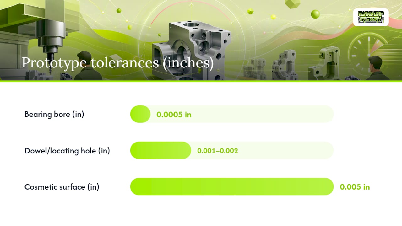
Tolerance guidance should match the feature's actual job. A bearing bore might need ±0.0005 inches to seat a press-fit bearing correctly. A dowel or locating hole typically holds ±0.001 to ±0.002 inches, worth checking against a reference for dowel pin hole tolerances before you spec it. Purely cosmetic surfaces can run standard shop tolerance, often ±0.005 inches, without any functional risk.
Request a material certificate or Certificate of Conformance whenever the prototype's alloy identity matters for a test report or a downstream customer approval, not just for routine form checks.
Lead Time and Cost Benchmarks: What Speeds or Premiums Apply
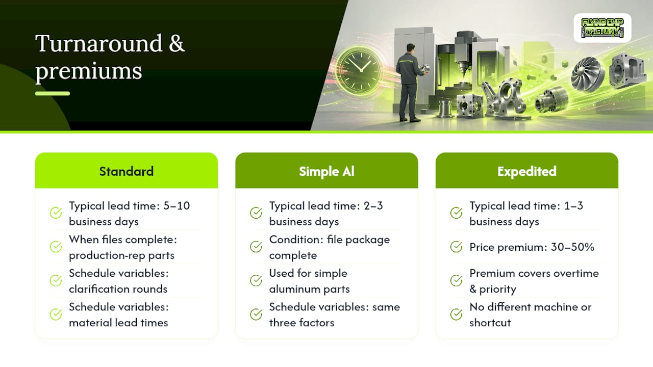
Realistic scheduling starts with knowing what "fast" actually costs. Rapid CNC prototyping typically delivers production-representative parts in 5 to 10 business days for standard turnaround, with simple aluminum parts often shipping in 2 to 3 days when the file package is complete.
Those numbers come from ypmfg's cost benchmarking for prototype-scale orders, and they shift with three main variables: incomplete files that trigger clarification rounds, material lead times for less common alloys, and setup complexity that requires multiple fixture changes.
Expedited service is available at most shops, sometimes as fast as 1 to 3 business days for simple parts, but it typically comes at a 30 to 50 percent premium. That premium pays for overtime labor and queue priority ahead of other customers' jobs, not for a different machine or a shortcut in the process.
CNC vs. 3D Printing: What to Use When
Neither method wins every job. The decision comes down to what you're actually testing.
- Choose CNC when you need production-grade material properties, tight tolerances, and a finish that matches the final part
- Choose additive printing when you need to check overall geometry or complex internal channels fast, and material properties don't matter yet
- Run a two-stage workflow by printing first for a quick geometry check, then machining a functional version in production alloy once the shape is locked, a sequence that reduces overall cost and speeds iteration compared to machining every revision
- Consider soft tooling or urethane casting once you need 10 to 50 units in a production-like plastic without cutting hard tooling yet
How to Shorten Lead Time: File Prep and Shop Evaluation
Getting parts faster mostly comes down to preparation, not luck.
- Submit a complete RFQ package: STEP file, dimensioned PDF drawing, material spec, and your test objective stated plainly.
- Ask the shop directly about turnaround for parts similar to yours, current material stock on hand, and whether they can run CMM inspection on the first article.
- Request separate pricing for "as-machined" versus a finished part with anodizing or bead blasting, so you can decide where to spend.
- Ask for a quick DFM check before committing. A five-minute look from a machinist often catches a tolerance conflict that would otherwise cost a day of back-and-forth later.
Shops built for prototype work, rather than pure production runs, tend to accept single-part orders and keep broader small-stock material selections on hand specifically to support this kind of fast turnaround.
Inspection and First-Article Verification: What to Request
A first-article report should include a dimensional table comparing every critical feature to your drawing, noted deviations, a surface finish check, and a clear pass or fail note on each callout.
- Request full CMM inspection when the part has tight-tolerance mating features or will feed into an assembly test
- Spot-check with calipers and pin gauges for lower-risk cosmetic or form-check parts
- Expect CMM inspection to add cost per part, but running it on the first one to three units before ordering the rest catches setup problems before they multiply across a batch
Once you have a clean first-article report, use its measured values, not just the drawing's nominal dimensions, as your baseline for production acceptance criteria going forward.
Flying Chip Factory Shop Perspective on Rapid CNC Prototypes
At Flying Chip Factory, quick quoting and direct machinist access aren't marketing lines. They're how the shop actually operates. When you send a file, you're talking to the person running the machine, not a sales layer between you and the spindle.
Shop-friendly parts, single setup, standard aluminum, clear tolerances, typically turn around in a few business days once the design is locked. More complex geometry takes longer, and we'll tell you that up front during quoting rather than after you've committed a schedule around it.
Author Perspective and Immediate Action Checklist
Pick rapid CNC as your primary route whenever the prototype's job is to prove something mechanical, not just look right on a shelf. Additive printing has its place, but if you're one iteration away from cutting production tooling, a machined part in real alloy tells you the truth faster than a rendering ever will.
Three things to do right now: prepare a STEP file with a dimensioned 2D drawing, list your top three functional features that actually need tight tolerances, and request a CMM first-article report before you commit to a full order. Flying Chip Factory can take that job.
— Drake
Get a Rapid CNC Prototype Quote from Flying Chip Factory
Flying Chip Factory is built around exactly the workflow this guide describes: fast quotes, a machinist you can actually talk to, and tight-tolerance capability proven on our own motorcycle parts, including the bolt-on E2 Kickstand line and the BDE Bar Mounts currently in development. We're not a call center between you and a spindle. We're the shop running it.

When you request a quote, send a STEP file, a dimensioned 2D drawing with your critical tolerances marked, your material spec, and a short note on what the test objective actually is. That last part matters more than people expect. Knowing whether you're checking fit, testing load, or verifying assembly lets us prioritize the fixturing and inspection that will actually answer your question, instead of treating every dimension as equally critical. If you're also weighing a short production run once the prototype checks out, our short-run CNC production guide covers that transition.
Head to Flying Chip Factory to submit your files and get a quote back fast.
Sources
- Rapid CNC Prototyping: Design to First Part (2026)
- CNC Machining Prototypes: When, Why, and How (Bravo Team)
- Prototyping with purpose (FuzeHub)