
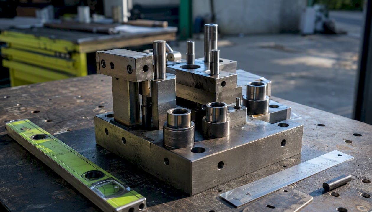
A well-designed drilling jig guarantees repeatable hole location and surface-normal accuracy while cutting setup time dramatically. The design priority order is non-negotiable: define your datums and bushing placement first, size your clamps to exceed the expected cutting thrust, and build in replaceable guide elements with clear chip evacuation paths from the start.
- Define datums and bushing placement first. Every locating pin, pad, and edge must be placed before you think about clamps or body geometry. The bushing position relative to the primary datum determines your positional tolerance budget for every hole in the jig.
- Size clamps to exceed cutting thrust. For a 19 mm hole in medium carbon steel, cutting thrust runs roughly 2.85–3.3 kN. FEA analysis on a lap-joint flange jig recommends clamping force at approximately three times that value, putting you in the 8.6–9.9 kN range. Document that number on the drawing.
- Design for replaceable guide elements and chip clearance. Press-fit bushings wear. Chip packing degrades accuracy faster than bushing wear in many shop environments. Both are maintenance problems, not design failures, if you plan for them upfront.
When to shop-build vs. outsource: If your tolerance is ±0.5 mm or looser and your run is under 20 parts, a plywood or aluminum plate jig built in-house is usually the right call. Tighter than ±0.1 mm positional tolerance, hardened bushings, or production quantities above 50 parts? Send it to a CNC job shop for a quote.
Key Takeaways
A well-designed drilling jig controls positional accuracy through rigid datums, correctly sized clamps, and replaceable guide elements, with chip clearance and a validation plan built in from the start.
| Point | Details |
|---|---|
| Datums and bushing placement first | Define all locating datums and bushing coordinates before designing clamps or body geometry. |
| Clamp force at 3× cutting thrust | Calculate cutting thrust for your drill size and material; set minimum clamp force at three times that value. |
| Match material to jig life | Use mild steel with hardened inserts for production jigs; aluminum or plywood is sufficient for prototype and low-volume work. |
| Design chip clearance in from the start | Add bushing standoff, angled ejection pockets, and drain holes before finalizing the jig body geometry. |
| Validate with a 10-part first article | Drill 10 parts, measure all hole positions, and confirm the positional range stays within 60% of drawing tolerance before full production. |
| Flying Chip Factory for outsourced jigs | Send a STEP file, GD&T drawing, tolerance stack-up, and run quantity to get a direct quote for CNC-machined prototype or production jigs. |
What is a drilling jig, and how does it differ from a fixture?
A drilling jig is a workholding device that simultaneously locates a workpiece, clamps it against cutting forces, and guides the cutting tool through a hardened bushing or journal. The guide element is what separates a jig from a fixture. A fixture locates and clamps, but the operator or machine positions the tool independently. A jig does all three.
| Attribute | Drilling Jig | Machining Fixture |
|---|---|---|
| Purpose | Locate, clamp, AND guide the tool | Locate and clamp only |
| Tool guidance | Hardened bushing or journal | None (machine positions tool) |
| Operator skill required | Lower (tool path is constrained) | Higher (relies on machine accuracy) |
| Typical use | Drilling, reaming, tapping | Milling, turning, grinding |
The practical use cases for a drilling jig break into four categories:
- Prototyping: Drill a consistent bolt-circle pattern across five prototype housings without setting up the CNC each time.
- Short-run production: Hold positional tolerance across a batch of 30–200 parts where full CNC fixturing is cost-prohibitive.
- Maintenance and repair: Re-drill worn or damaged holes to original location on field-returned parts.
- High-repeatability subassembly: Locate cross-holes or dowel holes in assemblies where mating parts are already machined to final dimension.
The measured cycle-time data makes the production case clearly: per-hole time drops from roughly 3.45–4.05 minutes on a manual table drill to 1.28–2.18 minutes with a properly designed jig. That gap compounds fast across a batch.
Anatomy of a drilling jig: body, locators, clamps, and guide elements
Jig body
The body is the structural backbone. Its job is to maintain the spatial relationship between locating features and bushing positions under drilling loads without deflecting enough to shift the hole location. Steel plate or weldment bodies are standard for production jigs. For prototype or low-volume work, a machined aluminum plate or even a well-braced plywood assembly can hold ±0.25 mm without issue.
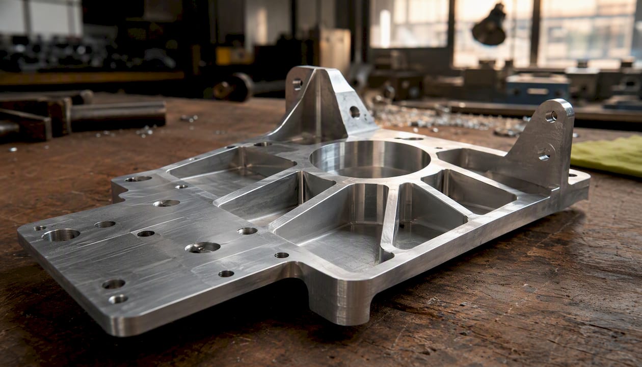
Stiffness targets depend on your tolerance. If you're holding ±0.1 mm, your body deflection budget is 0.02 mm. That number drives wall thickness and rib placement decisions early.
Locating devices
Locating pins, flat pads, and precision edges each eliminate specific degrees of freedom. A round pin in a precision hole eliminates two translational DOF. A flat pad eliminates one translational DOF (the normal direction). A diamond pin eliminates one rotational DOF without over-constraining the part. The goal is to constrain exactly six DOF, no more.
Precision requirements for locating pins are tighter than most engineers initially budget. A pin-to-hole clearance of 0.005–0.015 mm is typical for production jigs. Looser than 0.025 mm and the locating error starts eating into your positional tolerance budget in a way that's hard to recover from downstream.
Clamping devices
Clamps must resist drilling thrust in the axial direction and prevent rotation of the workpiece around the drill axis. Toggle clamps are the standard choice for production jigs because they apply consistent, repeatable force and release quickly. Screw clamps are slower but allow finer force adjustment, which is useful when clamping thin-walled or delicate parts where distortion is a risk.
Clamp sequencing matters as much as clamp type. Apply clamps in the order that pushes the workpiece against its primary datum first, then secondary, then tertiary. Reversing that order can lift the part off the primary datum before the secondary clamp seats it, introducing a tilt error that no bushing can correct.
Pro Tip: *Tighten clamps in the datum-contact sequence: primary first, secondary second, tertiary last. Then verify the part is still seated against all three datum surfaces before drilling.
Jig rigidity and correct clamp sequencing are often the deciding factors for long-term hole quality — even more than perfect bushing alignment. A jig that flexes under thrust or allows the workpiece to micro-shift between clamp tightening and drilling will produce drifting hole locations that look like a bushing problem but are actually a structural one.
Drill guide elements and indexing
Hardened drill bushings are the standard guide element. They come in press-fit (fixed) and renewable (slip-fit with a lock) configurations. Press-fit bushings suit low-volume jigs where the bushing outlasts the job. Renewable bushings are the right call for production jigs where bushing replacement is a scheduled maintenance event, not a rebuild.
Indexing mechanisms, whether a simple detent pin or a precision rotary plate, allow multiple holes to be drilled in a single clamping cycle. Indexed jigs reduce clamping cycles and improve positional repeatability in multi-hole patterns significantly. For a bolt-circle pattern, an indexing jig is almost always faster and more consistent than repositioning the part manually.
Which type of drilling jig fits your application?
Template and plate jigs
The simplest form: a flat plate with bushings at the hole locations, clamped or held against the workpiece by hand or simple clamps. Template jigs work well for thin sheet metal or flat stock where the part surface is the primary datum. Accuracy depends heavily on how well the template seats against the part. For anything requiring better than ±0.3 mm, add locating pins to the template rather than relying on edge contact alone.
On a concept sketch for a machinist, show the plate outline, bushing locations with coordinates from a single datum corner, bushing bore and OD, and any locating pin positions. That's the minimum to get a useful quote.
Box jigs
A box jig encloses the workpiece on multiple sides, allowing drilling from several faces in a single setup. The classic application is a shaft or block that needs cross-holes at precise angular relationships. Box jigs are heavier and more expensive to build than plate jigs, but they eliminate the repositioning error that accumulates when you re-clamp a part to drill from a second face.
The throughput tradeoff is real: a box jig takes longer to load and unload than a plate jig. For a 10-part prototype run, that's fine. For 500 parts per shift, evaluate whether a CNC machining center with a single fixture is faster overall.
Angle and vertical jigs
Angle jigs orient the drill at a fixed angle to the workpiece surface, typically 90° to a face that isn't horizontal on the drill press table. A dual-stop vertical drilling jig using T-tracks and sliding stops is an effective shop method for holding stock vertically and improving drill-press accuracy without a full machined fixture. For production use, a machined angle plate with hardened bushings and positive locating pins is the more repeatable solution.
On a concept sketch, show the workpiece orientation relative to the drill spindle axis, the angle of the jig body, and the bushing centerline. A machinist needs to see that the drill will clear the jig body at full depth.
Gang jigs
A gang jig positions multiple bushings in a row or pattern to drill several holes simultaneously or in rapid sequence without repositioning. The payoff is throughput: one clamping cycle, multiple holes, consistent spacing. The cost is flexibility. A gang jig is optimized for one part geometry. Any design change that shifts a hole location requires a new jig or a significant rework.
Gang jigs are worth the setup cost when you're drilling the same pattern on more than 100 parts and the holes are close enough together that a single drill head or quick repositioning between adjacent bushings is practical.
Indexing jigs
Indexing jigs use a detent, pin, or precision plate to rotate or translate the workpiece to successive hole positions. They're the right choice for bolt circles, equally spaced holes on a shaft, or any pattern where the hole-to-hole spacing is the critical dimension rather than the absolute position from a fixed datum. The indexing mechanism itself becomes the accuracy driver, so its manufacturing tolerance needs to be tighter than the hole-spacing tolerance you're trying to hold.
Step-by-step design checklist for a drilling jig
- Define requirements. Hole diameter, positional tolerance, surface finish at the hole entry, material being drilled, batch size, and expected jig life in cycles. These numbers drive every subsequent decision.
- Establish the primary datum. Pick the flattest, most accessible surface on the workpiece as the primary datum. The jig body's reference face machines to this datum. Everything else references off it.
- Lay out hole coordinates. Derive all hole centerline coordinates from the primary datum corner or datum axis. Never chain dimensions from hole to hole; always reference back to the datum. This keeps positional errors from stacking.
- Place bushings. Center each bushing bore on its hole coordinate. The bushing OD must clear the workpiece surface by at least 0.5 mm to allow chip evacuation. The bushing length should be at least 1.5× the drill diameter to provide adequate guidance.
- Size clamps. Calculate cutting thrust for your drill diameter and material. Set clamp force at a minimum of 3× that value. For a 19 mm drill in medium carbon steel, that means designing for roughly 8.6–9.9 kN of clamping force per the lap-joint flange study.
- Select materials. Match body material to stiffness and wear requirements (see the next section). Specify hardened bushings for any production run.
- Run a tolerance stack-up. Add up: locating pin clearance + bushing bore clearance + body deflection + thermal expansion if relevant. The sum must be less than your positional tolerance. If it isn't, tighten the tightest link in the chain first.
- Plan chip clearance and coolant paths. Add relief pockets around each bushing, angled ejection paths if the jig is enclosed, and drain holes if coolant is used.
- Write a validation plan. Specify what you'll measure, how many parts, and what the accept/reject criteria are before you cut the first chip on a production part.
Worked coordinate layout example: A plate jig for a rectangular block needs four holes on a 50 mm × 75 mm bolt circle, centered on the block. Primary datum is the bottom face; secondary datum is the left edge; tertiary datum is the front edge. Hole 1 is at X = 12.5 mm, Y = 18.75 mm from the datum corner. Hole 2 is at X = 62.5 mm, Y = 18.75 mm. Holes 3 and 4 mirror at Y = 56.25 mm. All four coordinates reference the same datum corner. The first bushing goes at Hole 1; verify its position with a CMM or height gauge before drilling the bushing plate.
Tolerance stack-up example: Positional tolerance on the drawing is ±0.15 mm. Locating pin clearance contributes ±0.008 mm. Bushing bore clearance (H7/f7 fit) contributes ±0.012 mm. Body deflection under load (from FEA or beam calculation) contributes ±0.020 mm. Total stack: ±0.040 mm. That leaves ±0.110 mm of margin, which is acceptable. If body deflection were ±0.080 mm instead, the stack would be ±0.100 mm, still within tolerance but with almost no margin for wear or thermal effects.
Material choices for shop jigs versus production jigs
The material decision comes down to four factors: stiffness under load, wear resistance at locating and guide surfaces, machinability during jig fabrication, and cost relative to the jig's expected life.
- Mild steel (1018, A36): The workhorse for production jig bodies. Good stiffness, welds easily, machines cleanly, and accepts surface treatments. Comparative analysis across candidate materials consistently shows steel produces lower deformation under typical drilling loads than aluminum or cast iron alternatives, per design review research. The downside is weight and corrosion in wet environments.
- Hardened steel inserts and bushings: Use at every wear surface: locating pins, bushing seats, and clamping pads. Through-hardening to 58–62 HRC at guide surfaces is standard for production jigs. The body stays mild steel; only the wear surfaces go hard.
- Aluminum (6061-T6 or 7075-T6): A practical choice for prototype jigs or any application where weight matters. Stiffness is lower than steel (roughly one-third the elastic modulus), so wall sections need to be thicker to hit the same deflection target. For aluminum jig components, the T6511 temper machines with less residual stress than standard T6, which matters when you're holding tight flatness on a locating face.
- Plywood and MDF: Effective for shop-built prototype jigs and low-volume work. A hardened-steel guide bonded to a wooden base produces a durable hand-drill jig that replicates drill-press accuracy for large or awkward parts. The steel guide does the precision work; the wood keeps the jig light and cheap. MDF is dimensionally stable but absorbs coolant; seal it if the jig will see any cutting fluid.
Manufacturability notes: Design locating faces to be machined in a single setup where possible. A face that requires repositioning to finish introduces a datum shift that's hard to measure and harder to correct. Use dowel pins for jig assembly rather than relying on fastener holes for alignment. Fastener holes have clearance; dowel pins don't.
When specifying surface treatments for jig components that see coolant, hardcoat anodize on aluminum locating surfaces adds meaningful wear resistance without changing the critical dimensions significantly, provided you account for the coating thickness in your tolerance budget.
When to use replaceable bushings vs. hardening the whole jig: If the jig will drill more than 500 holes in steel, use renewable bushings in hardened seats. If it's a 20-part prototype run in aluminum, a press-fit bushing in a mild steel plate is sufficient. Never harden the entire jig body; it makes rework and repair impractical.
How to design locating features and clamp layouts using the 3‑2‑1 principle
The 3-2-1 locating principle is the foundation of every well-constrained jig. Three points define the primary datum plane (eliminating three DOF: one translation, two rotations). Two points define the secondary datum (eliminating two more DOF: one translation, one rotation). One point defines the tertiary datum (eliminating the final translational DOF). Six points, six DOF eliminated, workpiece fully constrained.
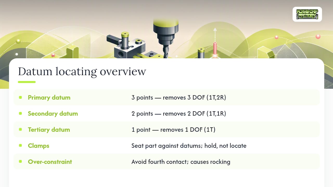
In practice: the primary datum is the workpiece's largest flat face, contacted by three support pads or pins arranged as far apart as possible to maximize stability. The secondary datum is typically a machined edge, contacted by two pins. The tertiary datum is a second edge or a single pin, contacted by one locator. The workpiece is pushed against all three datum surfaces by clamps, not by the locators themselves. Locators position; clamps hold.
For a rectangular block being drilled on its top face: three support pads on the bottom face (primary), two side pins on the left edge (secondary), one end pin on the front edge (tertiary). Clamps apply downward force to seat the block against the three bottom pads, and lateral force to seat it against the two side pins. The end pin just prevents forward sliding under drilling thrust.
Clamp layout guidance: Place clamps directly over or adjacent to support pads whenever possible. A clamp that's cantilevered far from a support pad creates a bending moment that can lift the part off the datum on the far side. For parts larger than 150 mm in any direction, use at least two clamps. Toggle clamps are preferred for production; they apply consistent force and release in one motion. Screw clamps are acceptable for prototyping but introduce operator variability in applied force.
Pro Tip: *For parts with variable stock thickness or cast surfaces that aren't perfectly flat, replace one or two of the three primary support pads with spring-loaded pins. The springs keep the part seated against the primary datum even when the surface isn't perfectly flat, preventing the rocking that causes datum errors.
The most common locating error in shop-built jigs isn't a wrong pin diameter or a misplaced pad — it's over-constraining the part. Adding a fourth contact point to the primary datum doesn't improve stability; it creates a three-legged stool problem where the part rocks between the four points depending on which three happen to be in contact. Three points define a plane. Four points fight over it.
Industry research on shaft drilling jigs stresses that balancing rigidity with adaptability is critical: the jig body should be stiff at datum contact points, while locating and clamping elements should be adjustable or replaceable to handle part variation across a production run.
How to choose and specify drill bushings
Bushing types and where each belongs
Headless press-fit bushings are the simplest: a plain cylinder pressed into a reamed hole in the jig plate. They're the right choice for low-volume jigs where the bushing will outlast the job. No locking mechanism means they can spin or walk out under high thrust if the press fit isn't tight enough.
Headed press-fit bushings add a flange that seats against the jig plate surface, preventing the bushing from being pushed through under axial load. Use these whenever the drill thrust is significant or the bushing plate is thin.
Renewable (slip-fit) bushings drop into a hardened liner that's permanently pressed into the jig. The bushing itself locks with a screw or cam. When it wears, you replace the bushing, not the liner. This is the correct choice for any jig expected to drill more than a few hundred holes in steel.
Liner bushings are the hardened seats for renewable bushings. They're pressed in once and stay for the life of the jig.
Bushing selection data
Worked sizing example: You need to drill a 12 mm hole to ±0.08 mm positional tolerance. Select a bushing with a 12 mm H7 bore (12.000/12.018 mm). The drill's h6 shank runs 11.989/12.000 mm. Clearance is 0.000–0.029 mm, keeping the drill centered within 0.015 mm of the bushing bore axis under normal conditions. Bushing length: 1.5 × 12 mm = 18 mm minimum. That 0.015 mm half-clearance fits comfortably within your ±0.080 mm tolerance budget, leaving room for locating pin clearance and body deflection.
For this application, a headed press-fit bushing in oil-hardened tool steel is appropriate for a prototype run. If the jig will drill 300+ parts, switch to a renewable bushing in a hardened liner. The liner gets reamed to a tighter tolerance than the bushing OD, typically an interference fit of 0.013–0.025 mm, to prevent rotation.
FEA on an indexing drill jig showed maximum deformation around 0.088 mm and a factor of safety above 3.5 for the chosen materials, confirming that properly specified bushings and body geometry can maintain positional accuracy under realistic drilling loads.
Designing for chip evacuation, coolant routing, and wear mitigation
Chip packing is one of the fastest ways to degrade jig accuracy. Chips forced between the bushing face and the workpiece surface act as a shim, lifting the drill off the surface and shifting the hole entry point. The fix is designed-in clearance, not periodic cleaning.
- Bushing standoff: Raise the bushing face 1–3 mm above the workpiece surface. This gap lets chips exit radially rather than packing under the bushing. For deep holes, increase the standoff to roughly 0.5× the drill diameter.
- Angled ejection pockets: In enclosed or box jigs, machine angled ramps or pockets around each bushing that direct chips toward a single exit point. A 30–45° ramp angle works well for most chip geometries.
- Service access: Any jig that encloses the workpiece needs a chip-clearing access point. A hinged panel or removable plate on the lowest face of the jig body lets an operator blow out chips between parts without disassembling the jig.
Coolant routing for wet drilling: If the jig is used with flood coolant, design drain holes at the lowest point of every enclosed cavity. A 6–8 mm drain hole is sufficient for most coolant flow rates. Route coolant away from locating surfaces; coolant pressure against a locating pad can lift the workpiece off the datum. For through-coolant drilling, the bushing bore must be sized to clear the drill's coolant channels without restricting flow.
Shop-built jigs with T-tracks benefit from the sliding stop and offset hole approach that keeps the jig adjustable for different stock sizes without a rebuild. The T-track channels also serve as natural chip evacuation paths when oriented correctly.
Maintenance checklist for bushing inspection:
- Inspect bushing bore diameter every 200 holes in steel (or 500 holes in aluminum) using a plug gauge or bore micrometer.
- Replace when bore diameter exceeds the nominal drill diameter plus 0.05 mm, or when visible bell-mouthing appears at the entry.
- Check bushing seating (press-fit or liner interference) every 50 production cycles by attempting to rotate the bushing by hand with the drill removed.
- Log replacement intervals by part number and material to build a predictive replacement schedule.
How to validate a jig and fix common failure modes
Validation checklist
- Datum verification: Before drilling any production parts, seat a known-good reference part (or a precision ground block matching the workpiece datum surfaces) in the jig. Verify contact at all three primary datum pads with a feeler gauge. Acceptable: 0.00 mm gap. Reject if any pad shows more than 0.005 mm gap.
- Bushing runout check: Insert a precision ground pin (matched to the bushing bore) and measure runout at the pin tip with a dial indicator. Acceptable: ≤0.010 mm TIR for production jigs, ≤0.025 mm for prototype jigs.
- First-article hole position check: Drill 3 parts. Measure each hole center location from the datum using a CMM or optical comparator. All holes must fall within 50% of the drawing positional tolerance on the first article. If they don't, find the cause before drilling more parts.
- Repeatability trial: Drill 10 parts, measure all hole positions, and calculate the range (max minus min) for each hole location. Acceptable range: ≤60% of the drawing positional tolerance. A properly designed jig should consistently hit the lower end of that range.
- Cycle time baseline: Record actual cycle time per part on the first 10-part run. Compare against the target. If cycle time is more than 20% above target, identify the bottleneck (clamping, chip clearing, or repositioning) and address it before full production.
Common failure modes and fixes
Slippage: The workpiece moves during drilling. Cause: insufficient clamping force or clamp applied in the wrong direction relative to thrust. Fix: recalculate clamp force (minimum 3× cutting thrust), reposition clamps closer to the datum pads, and verify clamp sequencing.
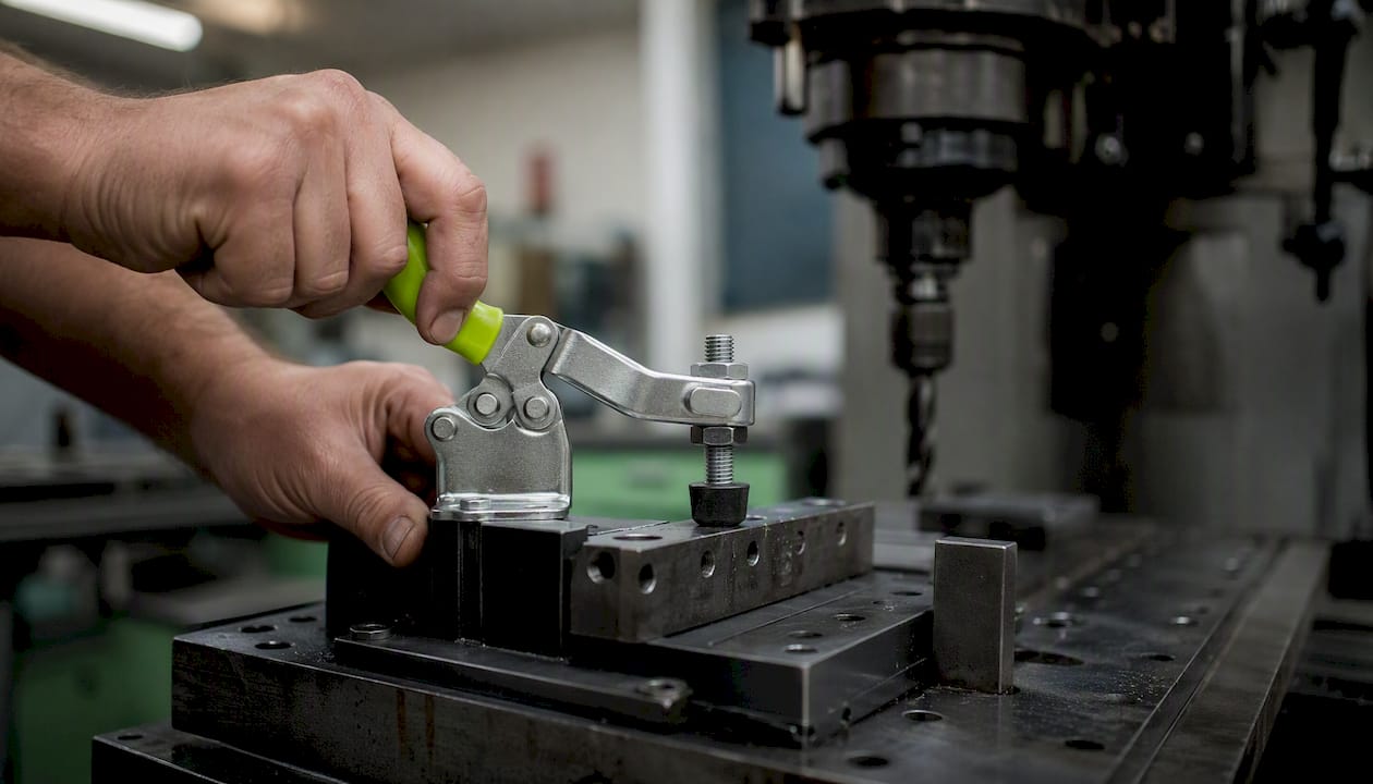
Vibration and chatter: Hole surface finish degrades, drill wanders. Cause: jig body flex, loose bushing, or workpiece not fully seated. Fix: add gussets or increase wall section on the jig body, check bushing press fit, and verify datum seating before each part.
Bushing wear: Holes drift over a production run. Cause: bushing bore worn beyond tolerance. Fix: replace bushing, log the interval, and switch to renewable bushings if press-fit bushings are wearing faster than expected.
Clamp distortion: Thin-walled parts deform under clamping force. Cause: clamp force exceeds part stiffness. Fix: add support pads directly under the clamped area, reduce clamp force, or switch to distributed clamping (wider pad contact area).
Mislocated datums: All holes are offset in the same direction. Cause: locating pin position error in the jig itself. Fix: re-measure pin positions from the jig's own datum, rework or replace the locating pins, and re-run the first-article check.
Use go/no-go gauges for quick shop-floor acceptance checks on hole diameter after drilling. They're faster than a bore micrometer for pass/fail decisions on production parts and catch oversize holes before they reach assembly.
Shop-ready manufacturability tips from Flying Chip Factory
Getting a jig design right on paper is half the job. Getting it right in the shop means giving your machinist enough information to build it without guessing.
Quoting checklist for engineers sending a jig design for fabrication:
- STEP or IGES file plus a dimensioned 2D drawing with GD&T callouts on all critical features (bushing bore positions, locating pin holes, datum faces).
- Critical datums called out explicitly on the drawing, not just implied by the coordinate system.
- Tolerances by feature type: positional tolerance on bushing centers, flatness on datum faces, diameter tolerance on pin holes and bushing seats.
- Material specification including temper (e.g., 6061-T6, not just "aluminum") and any heat treatment or surface finish requirements.
- Lot size and expected jig life in cycles, so the machinist can recommend bushing type and material.
- Preferred finish or coating (bare, anodized, black oxide) and whether any surfaces are to remain uncoated for dimensional reasons.
Prototype-first iteration cadence: Build the first jig in aluminum or mild steel without hardened bushings. Drill 10 parts, measure, and verify the tolerance stack holds. If it does, lock the bushing specifications and order hardened renewable bushings for the production version. If it doesn't, you've found the problem on a cheap prototype rather than a hardened production jig that costs three times as much to rework.
Practical shop tips:
- Keep a small inventory of standard renewable bushing sizes (6, 8, 10, 12, and 16 mm bore) and their matching liners. Standard sizes are available off the shelf; odd sizes add lead time and cost.
- Use hardened wear pads at all clamping contact points on the workpiece. Soft pads deform under repeated clamping and introduce a datum shift that accumulates over a production run.
- When communicating clamp force requirements to a machinist, give a number: "clamp force minimum 9 kN" is actionable. "Clamp firmly" is not.
- For slot-machined features in jig bodies (T-slots, chip clearance channels), specify the slot width tolerance and depth tolerance separately. A slot that's too wide loses its chip-directing function; one that's too deep weakens the jig body.
When to build a jig yourself versus having it machined
The honest answer depends on three variables: your positional tolerance, your expected run quantity, and what equipment you have access to.
Criteria that favor building it yourself:
- Positional tolerance is ±0.3 mm or looser.
- Run quantity is under 25 parts.
- The workpiece material is wood, plastic, or soft aluminum.
- You have a drill press, a flat reference surface, and basic layout tools.
- A shop-built jig with a sturdy base, adjustable clamps, and a guide mechanism is the right starting point. Test with scrap material to verify table squareness before committing to production dimensions.
Criteria that favor outsourcing to a CNC job shop:
- Positional tolerance tighter than ±0.15 mm.
- Run quantity above 50 parts, or the jig will be used repeatedly across multiple batches.
- The workpiece is steel, hardened material, or a complex geometry requiring a box or indexing jig.
- Hardened bushings, precision-reamed liner seats, or ground locating surfaces are required.
- You need the jig in less than a week and don't have the setup time to build it in-house.
Cost and turnaround drivers: The biggest cost driver in outsourced jig manufacturing is tolerance. Going from ±0.25 mm to ±0.05 mm on bushing position can double the machining time. Supply the machinist with your full tolerance stack-up calculation; a good shop will tell you if you're over-specifying and where you can relax a callout to save cost. Turnaround depends on material availability and queue depth, but a simple plate jig in aluminum or mild steel typically runs 3–5 business days at a CNC job shop with direct machinist access.
Flying Chip Factory builds jigs that work the first time
Prototype jigs and short-run fixtures are exactly what Flying Chip Factory does in Athens, Alabama. The shop handles CNC machining for prototyping, short-run production, and fixture fabrication, with direct access to the machinist handling your job. No account manager relay. No week-long email chains to clarify a tolerance callout.

When you send a jig design for a quote, include your STEP file, a dimensioned drawing with GD&T on critical features, your positional tolerance requirements, material preference, and expected run quantity. That's enough to get a real quote, not a placeholder. If your design has a tolerance that's tighter than necessary or a feature that adds cost without adding accuracy, you'll hear about it before the job starts, not after.
For jigs that need hardened bushing seats, precision-reamed locating pin holes, or ground datum faces, the shop has the equipment and the process knowledge to hold those features reliably. Request a quote at Flying Chip Factory and get a direct answer from the machinist who will cut your parts.
The case for designing jigs you can actually maintain
Most jig design guides spend their energy on the first build and almost none on what happens after part 50, which is backwards.
The jigs that cause the most production headaches aren't the ones that were designed wrong. They're the ones that were designed right for the first run and then slowly degraded because nobody planned for bushing replacement, wear pad inspection, or datum surface cleaning. A jig that holds ±0.08 mm on day one and ±0.25 mm on day 90 isn't a precision tool. It's a liability that produces bad parts gradually enough that nobody notices until a batch fails inspection.
The fix isn't complicated. Renewable bushings instead of press-fit. Hardened wear pads at every clamping contact point. A maintenance log attached to the jig itself, not buried in a shared drive. And a replacement interval based on actual measured wear, not a guess.
The other thing most guides understate: the 3-2-1 locating principle is not a suggestion. Engineers who add a fourth contact point to the primary datum because it "feels more stable" are creating a rocking constraint that introduces random positional error every time the part is loaded. Three points define a plane. That's geometry, not preference. The jig that feels wobbly with three pads and solid with four is telling you the workpiece surface isn't flat enough to be a primary datum, and the answer is to machine the workpiece datum, not add a fourth pad.
Finally, the decision to outsource jig manufacturing is often made too late. Engineers spend three weeks building a jig in-house that a CNC job shop could have delivered in four days, holding tighter tolerances, with hardened bushing seats already reamed to spec. The in-house build makes sense for a one-off prototype jig in aluminum. It stops making sense the moment you need hardened surfaces, ground datums, or a jig that will run 500 parts without rework.
Sources
- Design and Fabrication of Jig and Fixture for Drilling Machine in the Manufacturing Industry to Improve Time Productivity
- Design and Analysis of Drill Jig for Lap Joint Flange (ANSI B16.5)
- Innovative Design Idea of the Shaft Drilling Jigs and Fixture for Better Machining and Fabrication
- Dual-stop vertical drilling jig (Woodworker's Journal)
- How to build a drill press jig
- Hand drill jig for drill-press level accuracy (Obsessed Woodworking)