
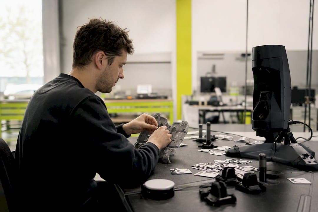
The fastest reliable path from scan data to a usable model is: clean the mesh, rebuild geometry through hybrid or human-guided surfacing, promote it to parametric CAD, then export as STEP, IGES, or a native file your downstream tools accept. Fully automatic mesh-to-solid conversion almost never survives contact with a real machine shop.
- DIY it if the part is simple, tolerances are loose, and you already know your CAD package.
- Hire a shop if you need tight tolerances, fast turnaround, or a part that has to machine correctly the first time.
- Next step: check your mesh for holes and noise before you touch any CAD tool, or send the raw scan to Flying Chip Factory for a quick file review.
Key Takeaways
Hybrid, human-guided surfacing consistently beats fully automatic mesh-to-solid conversion for building editable, production-ready CAD from scan data.
| Point | Details |
|---|---|
| Follow the workflow order | Capture, mesh, cleanup, feature extraction, parametric promotion, then validation and export. |
| Avoid full automation | Automatic mesh-to-solid conversion often produces heavy, uneditable geometry that can crash CAD software. |
| Match tools to the task | Use surfacing packages for hybrid modeling and CAD add-ins for handling large scan datasets without file bloat. |
| Budget by complexity, not size | Freeform and multi-part assemblies cost more and take longer than simple prismatic geometry. |
| Verify before you machine | Deviation maps, GD&T callouts, and an inspection report protect against downstream fit problems. |
| Outsource for tight tolerances | Flying Chip Factory rebuilds scans into parametric CAD with inspection reports and direct machinist access. |
What Does a Scan-to-CAD Workflow Actually Involve?
Every reverse engineering project moves through the same eight stages, whether you're rebuilding a bracket or an entire fixture assembly. Skipping one usually means redoing three.
- Capture — the scanner outputs a raw point cloud.
- Mesh generation — software stitches the cloud into a triangulated surface.
- Cleanup — you decimate, fill holes, and remove noise.
- Alignment — multiple scan passes get registered into one coordinate system.
- Feature extraction or surfacing — cross-sections and primitives get pulled from the mesh.
- Promotion to parametric solid — this is where the model becomes editable CAD.
- Validation — deviation analysis checks the solid against the original scan.
- Export — STEP, IGES, or native format hands the file to CAM or downstream engineering.
Deliverables shift at each stage: you start with a raw point cloud, get a watertight mesh by stage three, a parametric solid by stage six, and a STEP file plus inspection report by the end. Stages one through four are largely mechanical and increasingly automated. Stages five and six require actual CAD judgment. A reliable scan-to-CAD workflow leans on human-guided surfacing precisely because automatic mesh-to-solid conversion rarely produces something you can edit later.
How Do You Turn a 3D Scan Into an Editable CAD Model?
Converting a mesh into production-ready geometry is a sequence, not a single button press. Here's the operational version.
- Prep the part before you scan it. Matte down reflective surfaces, place reference targets, and plan for multiple passes on any part with hidden faces or deep pockets.
- Choose your capture method. Structured-light and laser scanners output PLY, OBJ, STL, or PTX files with high point density. Phone LiDAR works fine for rough concept geometry but struggles with sub-millimeter features.
- Generate and clean the mesh. Decimate to a manageable triangle count, fill holes, and register multiple scans into a single aligned mesh.
- Extract features. Pull cross-sections, fit primitives (cylinders, planes, fillets), and build NURBS surfaces where the geometry is freeform. This is hybrid modeling: the scan acts as a skeleton, not the final product.
- Promote to parametric CAD. Rebuild the part natively in your target package so it stays editable, not just a frozen surface.
- Validate. Run a deviation map comparing your new solid against the original mesh, and check fit against mating parts.
Practitioners at Verisurf describe successful reverse engineering as an iterative loop between the scan data and the CAD model, not a linear handoff. You compare, adjust, and compare again until the deviation map comes back clean.
Pro Tip: Never trust a single scan pass on a part with undercuts or internal pockets. Run a second pass at a different angle before you start cleanup. It's faster than discovering the gap after you've already built half the surfacing.
The temptation to let software fully automate mesh-to-solid conversion is understandable, but attempts at full automation typically produce heavy, nonparametric geometry that's hard to edit and can crash mainstream CAD packages outright, according to Autodesk's own workflow documentation. Hybrid modeling costs more time upfront and saves you from that failure mode entirely.
Which Software Tools Handle Each Part of the Job?
No single tool does capture, cleanup, surfacing, and inspection equally well. Match the task to the category.
- Scanner capture software controls point density, accuracy settings, and output format. This is where PLY, OBJ, STL, and PTX files originate, and where you decide whether the raw data is even worth processing further.
- Mesh editors and retopology tools handle decimation, hole-filling, and smoothing. This is grunt work, but skipping it means every downstream step inherits the noise.
- Reverse-engineering and surfacing packages are built specifically for imperfect, noisy scan data rather than artistic mesh work, according to QuickSurface, and they typically import STL, OBJ, PLY, or PTX files while exporting production-ready STEP or IGES.
- CAD add-ins let you work inside SOLIDWORKS or similar packages while storing the scan data externally, so a 40-million-point cloud doesn't crash your session. Polyga's Xtract3D links scan references into native features without bloating the file.
- Metrology and inspection tools verify the finished solid against the original scan with color deviation maps.
A phone LiDAR scanner is fine for a rough concept model. For anything going to a machinist with a tolerance callout, you need dedicated hardware and one of the surfacing packages above.
What Does 3D Scan to CAD Conversion Typically Cost?
Pricing tracks complexity more than part size. A simple prismatic bracket with a handful of planar faces might run a few hundred dollars and turn around in a couple of days. A complex freeform part, like a turbine blade or an organic housing, can be substantially more expensive once surfacing time and iteration rounds are factored in. Full assemblies with multiple mating parts tend to cost more, since every interface requires careful dimensional checking against neighboring parts.
Lead times follow the same pattern: a prototype-grade scan-to-CAD conversion can land in a few business days, while a full documentation package with a dimensional inspection report takes longer. Parts with internal passages or proprietary profiles sometimes require CT scanning or contact probing instead of optical scanning, which adds cost and engineering time.
Before you accept any quote, confirm:
- Deliverable file formats (STEP, IGES, native CAD)
- Stated tolerances, not just "high accuracy"
- Whether a dimensional inspection report is included
- The revision policy if the first pass misses a critical dimension
How Do You Confirm a Model Is Actually Production-Ready?
A pretty solid model isn't the same thing as a manufacturable one. Hybrid modeling preserves editability precisely because it rebuilds real features, planes, cylinders, fillets, instead of freezing a mesh into a dumb surface. If a machinist later needs a bore diameter changed by 0.005 inches, a parametric feature updates in seconds. A frozen mesh means starting over.
Verification has two parts. First, run a deviation or heat map comparing your CAD solid against the source scan, and apply GD&T callouts to any surface that mates with another part or carries a functional tolerance. Second, package the deliverables that actually protect you downstream:
- A dimensional inspection report showing scan-to-CAD deviation
- A revisioned CAD file with version history
- Material and finish notes, especially for parts that were reverse-engineered from a worn or damaged sample
Pro Tip: If you're reverse-engineering a broken part, measure the unworn reference surfaces first, not the worn ones. Wear patterns lie about the original geometry more often than people expect. For parts headed toward final machining, our anodize thickness guide covers how coating buildup affects your final dimensional callouts.
How Does Flying Chip Factory Handle Scan-to-CAD Projects?
Every job starts with an intake checklist: raw scan format, known tolerances, mating parts, and intended finish. That triage step catches half the rework before it starts, because a mesh with obvious gaps or a missing reference surface gets flagged before anyone opens a CAD package.
From there, the shop workflow runs mesh cleanup, hybrid rebuild in the target CAD package, a tolerance review against the intended use case, then CNC prep and inspection. Direct access to the machinist running your job means questions get answered in an afternoon instead of routed through three layers of account management.
A shop that iterates quickly between the physical part and the CAD model, with the machinist in the loop from day one, cuts out the back-and-forth that usually stalls manufacturability reviews. That's the whole reason Flying Chip Factory builds its own motorcycle parts in-house: it forces the process to survive real production, not just a rendering.
Our go/no-go gauge guide shows the kind of acceptance criteria we build into inspection reports.
What Most Guides Get Wrong About Scan-to-CAD
Most tutorials treat scan-to-CAD like a pipeline: scan in, solid out. That framing sells software licenses, but it ignores the actual bottleneck, which is judgment, not automation. Deciding which surfaces need true parametric features and which can stay as reference geometry takes an engineer who understands how the part will be used, not a smarter algorithm.
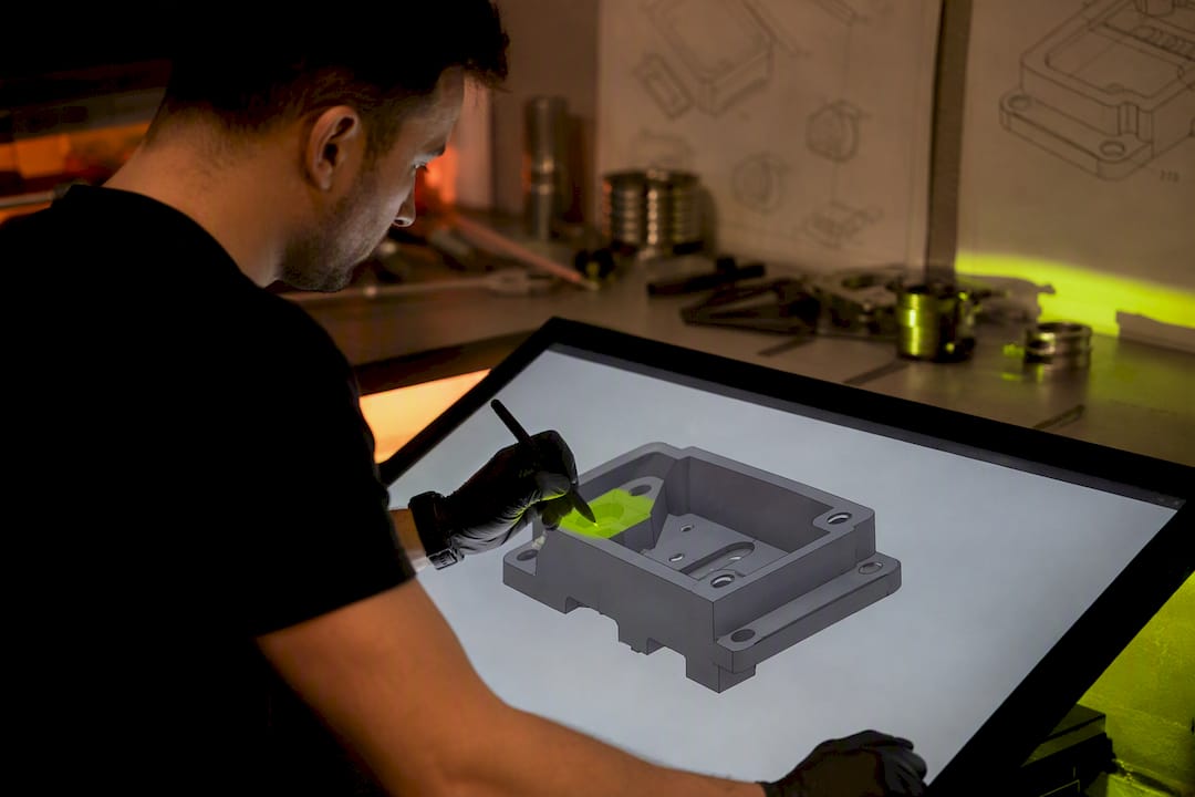
The overrated part of this whole conversation is fully automatic mesh-to-solid conversion. It demos beautifully and fails the moment you need to change a hole diameter six weeks later. Hybrid modeling looks slower on day one and wins every time a revision comes through, which for a production part is not a matter of if but when.
If you're doing this yourself, prioritize the mesh cleanup step over the software you use for surfacing. A clean, well-registered mesh forgives a mediocre surfacing tool. A noisy mesh defeats even the best one. For high-value geometry with real tolerances, the math on outsourcing usually favors hiring a shop over buying another software seat you'll use twice.
Get a Scan-to-CAD Quote From Flying Chip Factory
If you'd rather skip the surfacing learning curve entirely, Flying Chip Factory turns raw scan files into machinable, production-ready CAD faster than most engineers can finish cleaning up the mesh themselves. You get a parametric solid, STEP or IGES export, a dimensional inspection report, and CAM-prepped files ready for the machine, all reviewed by the same machinist who'll cut your part.

This works best for engineers who need tight tolerances on a short timeline, or makers with a broken or discontinued part that has to fit right the first time. Small manufacturers scanning fixtures or short-run tooling get the same benefit: no guesswork translated into a bad quote.
To request a quote, send your raw scan file (STL, OBJ, PLY, or PTX), any known critical dimensions, and your intended material. Start the conversation at Flying Chip Factory.
Frequently Asked Questions
Is 3D scan to CAD conversion the same as reverse engineering? They overlap heavily. Scan-to-CAD conversion is the technical process; reverse engineering parts usually implies you're also reconstructing intent, tolerances, and material specs from a worn or undocumented sample.
Which file format should I request from a scan-to-CAD service? STEP is the most widely accepted format for downstream CAD and CAM work. IGES still shows up in older pipelines, and some shops will also hand over a native file in your specific CAD package on request.
Can a phone with LiDAR replace a dedicated 3D scanner? For rough concept geometry, yes. For anything with a stated tolerance or a mating fit, phone LiDAR lacks the point density and accuracy that structured-light or laser scanners provide.
How long does a typical scan-to-CAD project take? A simple prototype conversion can turn around in a few business days. Full documentation packages with inspection reports, or parts requiring CT scanning for internal features, take longer.
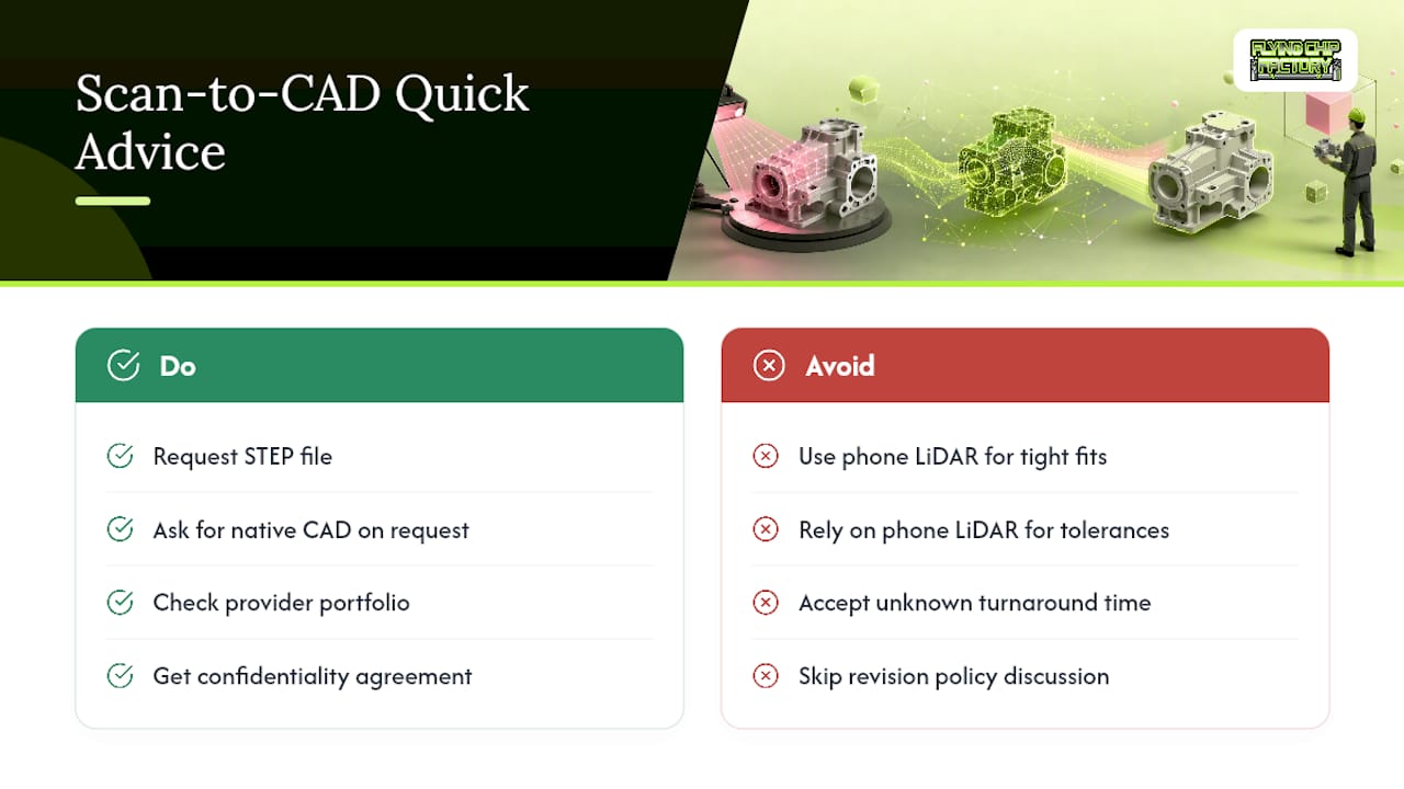
What should I look for when picking a scan-to-CAD service provider? Check their portfolio for parts similar in complexity to yours, ask about turnaround time and revision policy upfront, and confirm they'll sign a confidentiality agreement before you send proprietary geometry.
Sources
- QUICKSURFACE - From 3D scan to CAD
- 3D Scan to CAD Reverse Engineering - Verisurf
- Polyga Xtract3D 2 - Scan Data to CAD Simplified