
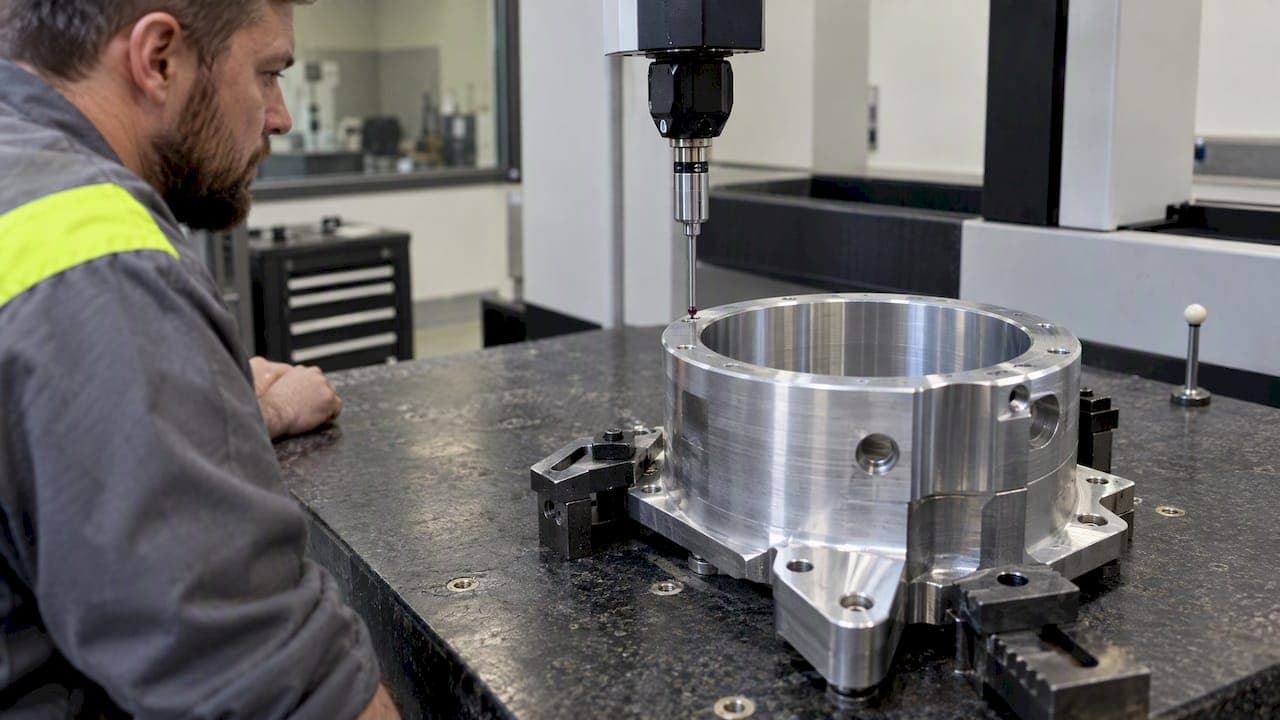
Perpendicularity tolerance controls how close a surface, axis, or line sits to a true 90 degree orientation relative to a datum. It is called out with the perpendicularity symbol in a feature control frame and defines either a zone between two parallel planes or a cylindrical zone around a derived axis. Before you release a drawing, confirm the datum is unambiguous and plan an inspection method that can resolve the tolerance with acceptable measurement uncertainty.
TL;DR:
- Accurate perpendicularity tolerances for small bore axes are typically between 0.02 and 0.05 millimeters, depending on size and function.
- Choosing the correct datum is crucial, with flat surfaces for planes and cylindrical features for axes, to ensure proper orientation constraints.
- Effective inspection requires well-spread sampling points, clear stylus protocols, and reporting measurement uncertainty to avoid false acceptances or rejections.
- Using appropriate tolerances and modifiers depends on function, feature size, and the measurement capability, with tighter limits only if confident in measurement accuracy.
- Poor datum realization and under-sampling are common causes of perpendicularity issues, emphasizing careful planning of fixture, measurement, and documentation.
What Perpendicularity Means in GD&T and How the Tolerance Zone Works
Perpendicularity is an orientation control: it governs angle, not location, and it only has meaning relative to a referenced datum. The symbol (⟂) sits in a feature control frame alongside a tolerance value and one or more datum letters.
For a flat surface, the tolerance zone is the space between two parallel planes, both oriented at exactly 90 degrees to the datum, separated by the tolerance value. Any point on the toleranced surface must fall inside that zone. For an axis or center line, such as a bore or a pin, the zone becomes cylindrical: a cylinder oriented at true 90 degrees to the datum, with a diameter equal to the tolerance value, inside which the derived axis must lie.

Datum selection changes what "90 degrees" means in practice. A datum plane gives a flat reference; a datum axis (often derived from a cylindrical feature) gives a rotational reference. ISO 1101 covers both cases, including median line and median plane callouts tied to a datum system, which is why the standard distinguishes surface callouts from axis callouts rather than treating them as interchangeable.
When to Choose Perpendicularity Over Angularity, Parallelism, or Profile
Perpendicularity is the right call when a feature must sit at exactly 90 degrees to a datum for the part to function: a mounting face that needs to seat flush, a bearing bore that must stay square to a shoulder, or a feature you intend to use as a secondary datum. Angularity covers the same geometric idea at any angle other than 90 or 0 degrees, and parallelism covers 0 degrees, so the choice among the three usually comes down to the nominal angle involved rather than a judgment call.
Profile tolerances come into play when orientation and form need to be controlled together, especially on a contoured or compound surface where a simple plane-to-plane check does not capture the full geometry. Position or profile is often the better choice when location and orientation interact, such as a hole pattern that must align to a mating part.
A few heuristics keep the symbol choice clean:
- If the nominal angle is 90 degrees and only orientation matters, use perpendicularity.
- If the surface has curvature or the spec needs to control size, form, and orientation together, use profile instead.
- If the feature's job is to locate a hole pattern or a mating boss, pair perpendicularity with position rather than trying to make one symbol do both jobs.
How to Specify Perpendicularity in a Feature Control Frame
A usable perpendicularity callout needs three things in the feature control frame, written in a fixed order, so both the machinist and the inspector read it the same way:
- The perpendicularity symbol (⟂), followed by the tolerance value, including any diameter symbol if the toleranced feature is an axis.
- One or more datum reference letters, in priority order (A, then B, then C), matching the datum reference frame shown elsewhere on the drawing.
- Any applicable material condition modifier, such as maximum material condition (MMC) or least material condition (LMC), appended to the tolerance value or the datum reference where it applies.
Datum order matters because the primary datum constrains the most degrees of freedom. A single flat datum plane is often enough for a surface callout; an axis callout referencing a cylindrical datum may need a secondary datum to fully orient the part in a fixture. MMC is appropriate when the orientation tolerance can legitimately grow as the feature departs from its maximum material size, which is common on pin or bore features captured by a mating part. For a mostly flat, orientation-only callout with no size trade-off, skip the modifier and keep the frame simple, since an unnecessary modifier only invites misreading on the shop floor.
Measuring Perpendicularity: Sampling Strategy, Probing, and Uncertainty
CMM inspection is where perpendicularity tolerances succeed or fail in practice, and the biggest variable is rarely the machine itself. NIST research on small circular features found that measurement uncertainty can shift dramatically depending on how many points are sampled and how they are angularly distributed around the feature. A three-point sampling strategy that happens to cluster on one side of a bore will produce a different answer than a well-spread eight-point pattern, even on the identical physical part.

Probe behavior adds another layer: approach direction, stylus length, and stylus type can introduce systematic lobing, and the same NIST work ties this lobing, along with machine error-correction software, directly to measurement uncertainty. Planning probe approach directions so errors do not correlate across sample points is as important as the point count itself.
On the acceptance side, NIST guidance on CMM uncertainty notes that gage-maker's rules have historically called for a 10:1 ratio between tolerance and measurement resolution, while modern practice often works with a 4:1 ratio and applies guard bands to cover the gap. Treat measurement uncertainty as part of tolerance allocation, not an afterthought.
A workable inspection sequence:
- Establish the datum exactly as called out, using the same feature and fixturing logic the drawing implies.
- Choose a sampling pattern with enough points, spread angularly, to resolve the tolerance zone rather than guess at it.
- Document stylus configuration and approach directions so the inspection is repeatable.
- Compute and report an uncertainty figure alongside the measured value, then apply a guard band before accepting or rejecting the part.
Pro Tip: Run the same feature with two different sampling patterns before finalizing an inspection procedure; a large spread between results is a sign your sampling strategy, not your part, needs work.
Worked Examples: What Counts as a Reasonable Perpendicularity Tolerance
Reasonable tolerance values depend on function, feature size, and what your inspection equipment can actually resolve, but a few common cases illustrate the logic.
- Small bore axis to a datum plane: for a bore under 10 millimeters in diameter that locates a bearing or bushing, a perpendicularity tolerance in the range of 0.02 to 0.05 millimeters on the axis is common, tight enough to prevent binding but loose enough to inspect reliably without pushing into the uncertainty territory the NIST sampling data warns about.
- Mating surface on a bracket or clamp interface: a flat surface that seats against another part under load typically works well with 0.05 to 0.1 millimeters of perpendicularity to the mounting datum, which keeps clamping force even across the interface without demanding finishing operations beyond standard milling.
- High-load or bearing interfaces: when the feature carries significant radial or axial load, tighten toward the lower end of these ranges and confirm your gage ratio still supports the tighter number, since a tolerance that cannot be measured with confidence is not functionally tighter, only harder to verify.
Converting a fit requirement into a perpendicularity number starts with the allowable misalignment at the mating interface, then backs out a tolerance that an achievable sampling strategy can confirm.
Common Mistakes and a Pre-Inspection Checklist
Most perpendicularity problems trace back to three mistakes: referencing the wrong datum feature, confusing an orientation callout with a form control like flatness (our flatness versus parallelism breakdown covers this distinction in more depth), and under-sampling during CMM runs to save cycle time.
Watch for these red flags during inspection:
- Datum realization that shifts between setups, often from a fixture that does not constrain the same degrees of freedom the drawing implies.
- Stylus or probe lobing patterns that repeat across multiple parts, suggesting a probing issue rather than a part issue.
- A measurement report with no stated uncertainty, which leaves acceptance decisions unverifiable.
Pro Tip: Before releasing a drawing, walk through datum choice, tolerance value, modifier use, sampling plan, uncertainty budget, and guard band in that order; skipping any one of these six is the most common source of rework.
How We Approach Perpendicularity Callouts on Prototype Jobs
When we machine a prototype or short-run part with a perpendicularity callout, we start by confirming how the datum will be realized in the fixture, since a callout that looks clean on paper can be ambiguous once a part is clamped; understanding various precision glass measurement methods helps ensure tight tolerances on delicate components. We flag callouts that are tighter than our measurement setup can confidently verify and talk through alternatives rather than guessing at acceptance. Sending clear CAD views, the full feature control frame, and any inspection notes up front shortens quoting and cuts down on revision cycles once machining starts.
Three Actions to Take Before You Release the Drawing
Perpendicularity callouts fail less often from bad machining than from unclear specification. Pick a datum that reflects how the part actually gets constrained in use, and write it into the feature control frame without ambiguity. Plan your inspection with an explicit sampling strategy and a stated uncertainty, not a single quick probe pass. Then tell your shop what function the tolerance protects and what guard band you can live with, so they can push back on a number that cannot be reliably measured.
— Drake
Get Perpendicularity-Sensitive Parts Machined Right the First Time
A tight perpendicularity callout only pays off if the shop machining it understands why the number matters, not just what it says. We design, machine, and ship both custom prototype work and parts from one shop, which means the same person reading your feature control frame is the one setting up the fixture and running the inspection, with no sales layer in between to lose detail in translation.

When you send a quote request for prototype machining, short-run production, or fixture and bracket work, include your drawing with datums called out, the critical tolerances flagged, and any inspection requirements you need documented. If you want to see an example of a precision CNC part we build in-house, our E2 Kickstand page shows the level of fit and finish we hold on production parts. Ready to get a job quoted? Start a quote request and we will walk through datum and tolerance questions directly with you before anything hits the mill.
FAQ
What is a reasonable perpendicularity tolerance?
A reasonable value depends on feature size and function: small bores locating bearings often run 0.02 to 0.05 millimeters, while mating surfaces on brackets or clamps commonly use 0.05 to 0.1 millimeters. Tighter values are reasonable only when your inspection setup can resolve them with an acceptable measurement uncertainty.
What is the 3-2-1 rule in GD&T?
The 3-2-1 rule describes a fixturing principle, not a tolerance symbol: three points constrain a primary plane, two points constrain a secondary plane, and one point constrains a tertiary plane, together removing all six degrees of freedom. It underpins how datums get physically realized in a fixture during both machining and inspection.
How do you calculate geometric tolerance?
Geometric tolerances are typically derived from the functional fit requirement at an interface, then checked against what your sampling strategy and gage can measure within an acceptable uncertainty, per NIST guidance on gage ratios. There is no single formula; it is a trade-off between function, manufacturing capability, and inspection confidence.
When should you use perpendicularity in GD&T?
Use perpendicularity when a feature must sit at exactly 90 degrees to a datum for the part to function correctly, such as a mounting face or a bearing bore. If the nominal angle is something other than 90 degrees, angularity applies instead, and parallelism covers the 0 degree case.
Sources
- Estimation of the Measurement Uncertainty of Small Circular Features Measured by Coordinate Measuring Machines
- ISO 1101:2017 — Geometrical product specifications (GPS) — Geometrical tolerancing — Tolerances of form, orientation, location and run-out