
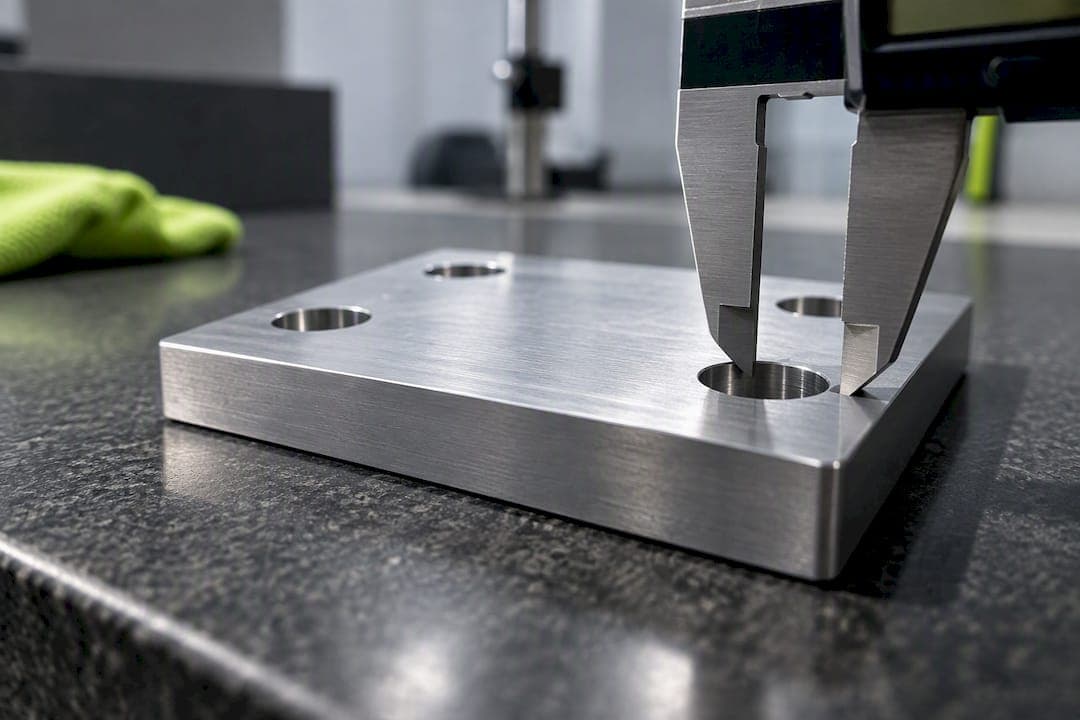
True position is the GD&T control that defines how far a hole, pin, or feature's actual center can drift from its theoretically exact location, measured inside a round tolerance zone rather than a square box. It's the standard tool for controlling location on interchangeable parts, governed by ASME Y14.5, and verified with functional gages, coordinate measuring machines (CMMs), or vision systems.
TL;DR:
- True position uses a circular tolerance zone, not independent X and Y limits, to account for round feature drift in all directions evenly.
- Calculating position error involves measuring dx and dy from the nominal, squaring, summing, square-rooting, and then doubling to get the diametral deviation.
- Bonus tolerance applies at MMC and LMC, increasing the permissible variation based on actual feature size, with roughly 57% more tolerance when used correctly.
- The inspection method—gauge, CMM, or vision system—should match the part volume and datum setup, as mismatches can cause false failures.
- Correct datum setup, proper measurement, and applying bonus tolerance are essential for accurate true position verification on parts.
What Is True Position in GD&T?
True position isn't a measurement you take. It's a comparison: where a feature's center actually landed versus where the drawing said it had to be, expressed inside a circular or cylindrical tolerance zone instead of a rectangular one.
The formal definition, per GD&T Basics, is that true position is a location control expressed as a diametral tolerance zone around a nominal, or "true," location. The word "true" refers to the theoretical exact point, defined by basic dimensions on the drawing. The tolerance zone is the allowable wobble room around that point. People often shorten "position tolerance" to "true position," and in shop conversation the two terms get used interchangeably, but the standard term in ASME Y14.5 is simply position.
The best way to picture it is a dartboard. The bullseye is the true, theoretical location. Every ring around it represents a boundary the dart can land inside and still count. That analogy, popularized by GD&T Basics, fixes the single biggest misunderstanding beginners have: treating position as a simple X/Y coordinate check with independent plus/minus limits on each axis, rather than a single circular zone that the feature's axis has to fall inside, no matter which direction it drifted.
Why a circle instead of a square? Because most located features, holes, pins, bosses, are round, and a round feature can drift in any direction with equal consequence to fit and function. A square tolerance zone built from independent X and Y limits lets a feature drift twice as far in the corners as it does straight along an axis, which has nothing to do with how the part actually mates with its neighbor. A cylindrical zone treats every direction of drift the same way a bolt or dowel actually experiences it.
A few things worth locking in early:
- The position symbol looks like a small target circle divided into quadrants, distinct from concentricity or symmetry symbols.
- "True position" is the informal name; "position tolerance" is the ASME Y14.5 term you'll see in specs and callouts.
- The zone is diametral, meaning the stated tolerance value is the full zone diameter, not a radius.
- Position is almost always the right choice for holes, pins, slots, and any feature whose job is to mate with something else.
Coordinate tolerancing (plain ± dimensions) still shows up on older drawings and in some fixture work, but it produces a boxier, less functionally accurate zone. That comparison matters enough that it gets its own breakdown further down.
How Does True Position Appear on a Drawing?
Two things carry the information: basic dimensions that locate the feature, and a feature control frame that states the tolerance and the rules for evaluating it.
Basic dimensions are the numbers inside a box on the drawing. They define the theoretical exact location, and by definition they carry zero tolerance of their own. If you see a boxed "2.500," that's not a typo missing its plus/minus. It's telling you: this is the target, and the actual allowed variation lives somewhere else, in the feature control frame.
The feature control frame (FCF) is the compartmentalized box that actually states the requirement. Reading one, left to right, generally goes like this:
- The geometric characteristic symbol comes first, the position target-circle icon in this case.
- The tolerance zone shape and value follow, often preceded by a diameter symbol (⌀) since the zone is cylindrical.
- A material condition modifier may follow the tolerance value, most commonly Ⓜ for maximum material condition (MMC) or Ⓛ for least material condition (LMC). No symbol present means the default, regardless of feature.
- Datum references come last, usually one to three letters (A, B, C) in their own compartments, read left to right as primary, secondary, and tertiary.
Datum order isn't cosmetic. The primary datum controls orientation and gets locked down first during inspection setup, typically fixing three degrees of freedom. The secondary datum locks rotation, and the tertiary locks the last remaining degree. Swap the order and you get a different measurement setup, and sometimes a different pass/fail result, on the exact same physical part. If a drawing calls out position relative to datums A, B, C, the inspector sets the part on datum A first, aligns to B second, and locks rotation to C last. Get that sequence wrong and your dx/dy numbers won't match what the designer intended.
Material condition symbols also change what the tolerance means at inspection time, which is worth understanding before you touch a calculator, since it affects every number in the next section.
How Do You Calculate True Position?
The formula for 2D position error is straightforward once you know what dx and dy mean:
P = 2 × √(dx² + dy²)
For features located in three dimensions, the formula extends the same way, per MakerStage's breakdown of the position formula:
P = 2 × √(dx² + dy² + dz²)
Here, dx is the measured X location minus the nominal (basic) X location, and dy is the same for Y. The "2×" is there because the tolerance is diametral, a full zone diameter, while dx and dy describe a radius of deviation. Forget that multiplier and you'll calculate a position error that looks like it passes when the part is actually out of spec.
Worked example. A drawing calls for a hole at basic location X = 1.000, Y = 1.000, with a position tolerance of ⌀0.010 at MMC, referencing datums A, B, C. A CMM measures the actual hole center at X = 1.004, Y = 0.997.
- dx = 1.004 − 1.000 = 0.004
- dy = 0.997 − 1.000 = −0.003
- P = 2 × √(0.004² + 0.003²) = 2 × √(0.000016 + 0.000009) = 2 × √0.000025 = 2 × 0.005 = 0.010
The calculated position error lands exactly at 0.010, right at the stated tolerance, with zero bonus applied. If the hole's actual measured diameter came in larger than its MMC size, bonus tolerance would stretch that allowed 0.010 further, which is exactly what the next section walks through.
A few habits keep this calculation from going wrong in practice:
- Always square dx and dy before adding them; a sign error on dy doesn't matter once it's squared, but forgetting to square it entirely does.
- Double the square root, not the sum inside it, since the tolerance is diametral.
- For patterns with more than one hole, calculate each hole's position error independently against the same datum-referenced nominal grid.
- Never average positional errors across a pattern. Every hole either passes its own zone or it doesn't.
Material Condition Modifiers: RFS, MMC, and Bonus Tolerance
RFS (regardless of feature size) is the default in ASME Y14.5 when no modifier symbol appears in the feature control frame. Under RFS, the stated position tolerance is fixed no matter what size the actual feature measures at. No bonus, no exceptions.
MMC (maximum material condition), marked with an Ⓜ, is the condition where a feature contains the most material: the smallest allowable diameter for a hole, or the largest allowable diameter for a pin or boss. Calling out position at MMC unlocks bonus tolerance.
LMC (least material condition), marked with an Ⓛ, is the opposite extreme: the largest hole or smallest pin. It's used less often, mostly on features where minimum wall thickness or material retention matters more than assembly clearance.
The bonus tolerance formula is simple, and it's one of the most useful shortcuts in GD&T:
Bonus = Actual size − MMC size (bonus can never go negative)
Allowed position tolerance = Stated tolerance + Bonus
Pro Tip: Bonus tolerance only grows in the direction that helps assembly. A hole specified at MMC gets bonus as it gets bigger (more clearance to work with); a pin specified at MMC gets bonus as it gets smaller. Mixing that up is a common rookie mistake on inspection reports.
Statistic to keep in mind: switching an equivalent ± coordinate callout over to a true position callout at MMC typically opens up roughly 57% more usable tolerance area for the same functional fit requirement. That's not a rounding difference. On a bolt-pattern part run in the hundreds, that gap is the difference between a scrap pile and a clean pass rate.
Worked bonus example. A hole is specified ⌀0.500 to ⌀0.510, position ⌀0.010 at MMC. MMC for a hole is the smallest allowed size, so MMC = ⌀0.500. The actual part measures the hole at ⌀0.506.
Bonus = 0.506 − 0.500 = 0.006 Allowed position = 0.010 + 0.006 = 0.016
If that same hole's calculated position error (using the formula above) came out to 0.014, it fails under RFS logic but passes comfortably once the MMC bonus is applied. This is exactly why the modifier symbol in the feature control frame isn't a minor footnote. It changes the pass/fail line entirely.
Virtual condition ties this together on the assembly side: it's the worst-case combined effect of size and position tolerance, and it defines the boundary a functional gage pin has to represent. For a hole at MMC, virtual condition equals MMC size minus the stated position tolerance, the smallest effective opening a mating pin will ever see.

Gauge, CMM, or Vision System: Which Inspection Method Fits?
Position tolerance means nothing until someone measures it, and the method you choose changes both the cost and the kind of data you get back.
Functional gaging uses a custom-built gage, often a plate with pins sized to virtual condition, that either accepts the part or rejects it. It's fast, it's consistent across operators, and it directly simulates the mating condition the part will face in assembly. The tradeoff is up-front cost and lead time: building a dedicated gage for a one-off prototype rarely makes economic sense, and a gage only answers pass/fail, not by how much a feature missed.
CMMs probe the actual feature and report real coordinate data, meaning you get dx and dy for every hole in a pattern, not just a pass/fail light. That's what Keyence's breakdown of position measurement points to as the CMM's real advantage: precision and full traceability, especially valuable when a pattern has several features and you need to know which one is actually drifting and by how much. The tradeoff is cycle time and equipment cost, though for short runs and prototypes that flexibility usually outweighs the speed of a gage.
Vision and laser systems sit somewhere in between. Software-driven optical systems, like the tools VISIONx builds for position measurement, can check position on the shop floor in seconds and output automated pass/fail reports without a dedicated fixture for every part number. They're a strong fit for high-volume repetitive checks where a CMM cycle would slow the line down.
A few rules of thumb for choosing:
- Use functional gaging for high-volume production where the same feature gets checked thousands of times and the mating condition is well established.
- Use a CMM for prototypes, first-article inspection, and any pattern where you need to know which specific hole is drifting.
- Use vision or laser systems for fast in-process checks on the shop floor, especially where traceable digital records matter.
- Match the reported units and datum setup across methods; a part that passes on a CMM but fails a gage almost always traces back to a datum or fixturing mismatch, not a real disagreement about the part.
Solid shop-floor quality practices, the kind Mestric outlines for manufacturing quality control, matter as much as the equipment itself. A CMM programmed against the wrong datum scheme will confidently report a wrong number.
Why Do Hole Patterns Fail True Position?
Most position failures trace back to one of three things: a datum setup problem, a measurement error, or a real part deviation. Working through them in that order saves time.
- Verify the datum setup first. Confirm the part is seated on the correct primary datum surface, aligned to the secondary, and rotationally locked to the tertiary, in that exact order. A part measured against the wrong datum reference frame can show a "failure" that isn't real.
- Check the measurement method itself. Confirm probe calibration on a CMM, or clean pin engagement on a functional gage. A dirty or worn gage pin reads a false fail more often than any actual part defect.
- Recheck for MMC bonus before calling it a reject. If the feature control frame carries an Ⓜ, measure the actual feature size and calculate whether bonus tolerance pulls a marginal failure back into a pass.
- Look at combined dx/dy, not single-axis drift. A part that's off in X but centered in Y might look fine on a quick caliper check of one axis, but position is calculated from both axes together, and that's where teams get tripped up.
That last point deserves its own warning. Correcting a single axis in isolation can make one hole's individual reading look better while making the pattern's overall position worse, because true position is computed from combined dx/dy across the whole pattern, not axis by axis. If two holes in a four-hole bolt pattern are both drifting in the same diagonal direction, nudging the fixture to fix one hole's X reading can throw the other three further off if the underlying cause was a rotational offset, not a simple X shift.
Worked troubleshooting example. A 4-hole pattern shows three holes passing and one failing position at 0.013 against a 0.010 RFS tolerance. Datum check confirms correct setup. The failing hole's dx/dy shows nearly equal drift in both X and Y, at 45 degrees, a strong signal of fixture rotation rather than a single misplaced hole. The fix: check the fixture's clocking pin or locating feature for wear, not the CNC program's individual hole coordinates.
Applying True Position on Real Prototype and Short-Run Parts
Working prototypes and short production runs at Flying Chip Factory means seeing position tolerance decisions made under real time and cost pressure, not in a textbook vacuum. The gap between a spec sheet and a working part usually shows up first in a bolt pattern.
For bolt patterns and alignment bores meant to accept off-the-shelf fasteners or dowels, MMC almost always makes more practical sense than RFS. It reflects how the parts actually assemble, since a slightly oversized hole genuinely does tolerate more positional drift without hurting fit, and it tends to produce more usable parts from the same run without loosening the functional requirement. RFS earns its place when a feature's exact location matters regardless of its size, commonly on precision alignment features or where a mating part has zero clearance to spare.
On the measurement side, prototype and short-run quantities usually make a CMM check the right call over building a dedicated functional gage. It's a lot easier to justify a CMM cycle on five parts than a custom gage that only pays off at production volume. When we report inspection results back to a designer, we send the actual dx/dy numbers per hole, not just a pass/fail stamp, since that data tells the designer whether a near-miss is a fixture problem or a real datum strategy issue. If your design carries tolerances tight enough that this kind of feedback loop matters, our guide on tight tolerance machining covers the cost and yield tradeoffs worth knowing before the first part gets cut.
True Position Checklist Before You Sign Off a Drawing
Run through these before releasing a drawing or signing off an inspection report:
- Confirm every located feature has boxed basic dimensions with no tolerance value inside the box itself.
- Verify the datum reference frame order (primary, secondary, tertiary) matches how the part actually gets fixtured for inspection.
- Decide RFS, MMC, or LMC deliberately for each feature, based on function, not habit.
- Calculate bonus tolerance whenever an MMC or LMC symbol appears, before calling a marginal part a reject.
- Match the inspection method (gage, CMM, or vision system) to the part quantity and the tolerance criticality.
- When in doubt on interpretation, the definitive rules live in ASME Y14.5.
| Takeaway | Why it matters |
|---|---|
| Basics carry no tolerance | The FCF is the only place the actual allowance lives |
| Datum order changes results | Same part, different setup, different number |
| MMC unlocks bonus | Bonus = Actual size − MMC, added to stated tolerance |
| Combined dx/dy, not single-axis | Fixing one axis can worsen the pattern overall |
| Method should match volume | Gage for production, CMM for prototypes and patterns |
A Machinist's Take on Designer-Shop Collaboration
The tightest position tolerance on a drawing is worthless if nobody checks whether the fixturing can actually hold the part to that datum scheme in the real world. Designers reach for RFS by default because it feels safer on paper, and then get surprised when a short run comes back with more rejects than expected, rejects that MMC bonus would have quietly absorbed without loosening anything that actually mattered for fit.
The fix is almost always timing, not tooling. Loop the machinist in while the datum structure is still a sketch, not after the drawing's released. A test part run against a proposed datum scheme tells you more in an afternoon than another round of tolerance stack-up math on a screen. Send the drawing early, ask what the fixture setup will actually look like, and adjust the datum order if the answer surprises you.
— Drake
Get Prototype Parts Made and Inspected Right the First Time
Reading a feature control frame correctly is one thing. Getting a part machined to it, and verified against it, is another. Flying Chip Factory runs prototype machining, short-run production, and custom fixtures, brackets, and support parts through a single shop, with no sales layer between your drawing and the machinist actually cutting it.

That direct line matters most when a position callout is borderline or a datum scheme needs a second look before a full run gets committed. Send us your drawing, and questions about datum setup, material condition choices, or bonus tolerance calculations get answered by the person actually running the machine, not relayed through a project manager. If you're building or repairing an electric mini dirt bike in the meantime, the E2 Kickstand is a CNC-machined, bolt-on part available online. For a prototyping quote, test part, or an inspection question on your own drawing, start at the Flying Chip Factory shop page.
Sources
The definitive source for every rule discussed here is ASME Y14.5, the standard governing position, datums, and material condition. For calculation walkthroughs and the MMC bonus formula in more depth, MakerStage's true position resource is a solid follow-up. GD&T Basics covers the dartboard analogy and the position-versus-coordinate-tolerancing distinction in plain language, useful if you're teaching this to someone else.
- ASME Y14.5 dimensioning and tolerancing
- True Position: Calculation, MMC Bonus & Examples (2026)
- True Position - Position Tolerance
FAQ
What is the formula for true position?
The 2D formula is P = 2 × √(dx² + dy²), where dx and dy are the measured location minus the nominal basic dimension on each axis. For three-dimensional features, it extends to P = 2 × √(dx² + dy² + dz²).
How do you interpret true position results?
Compare the calculated P value against the stated tolerance in the feature control frame; if P is equal to or less than the tolerance, the feature passes. If the callout includes an MMC or LMC modifier, add any earned bonus tolerance (actual size minus MMC size) to the stated tolerance before making that comparison.
How do you understand true position in GD&T?
Picture a dartboard: the bullseye is the theoretical exact location defined by basic dimensions, and the surrounding ring is the diametral tolerance zone the feature's actual center has to land inside. That mental model, popularized by GD&T Basics, avoids the common mistake of treating it like an independent X and Y box check.
Can you explain GD&T in a simple way?
GD&T is a system of symbols and rules for describing how a part is allowed to vary in shape, size, and location while still functioning correctly, rather than relying on plain plus-or-minus dimensions alone. True position is one control within that system, specifically the one that governs where a hole or pin's center is allowed to sit relative to its nominal location.
Does Flying Chip Factory help verify true position on prototype parts?
Yes. Flying Chip Factory machines prototype and short-run parts and reports inspection results including per-hole dx/dy data, not just a pass/fail stamp, so designers can tell whether a near-miss traces back to a fixture issue or a real datum strategy problem. Current pricing and service details are listed on the Flying Chip Factory site.