
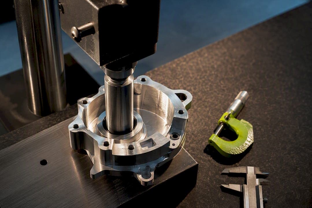
Press-fit tolerance is the paired tolerance band on a hole and a shaft that guarantees interference across every part you make. The design rule is simple to state and easy to get wrong: pick an ISO or ANSI fit class that meets the minimum interference the joint needs to do its job, then verify the maximum interference against your material and geometry using Lamé's equations or FEA. Skip either half, and you either get a joint that spins loose or a hub that cracks on the press.
TL;DR:
- The maximum interference amount is critical because excessive interference can cause hub deformation or galling, rather than just a loose fit.
- Shop practices such as proper chamfering, lubrication, controlled pressing speed, and matching tolerance assignment to equipment capabilities significantly reduce press fit failures.
- Interference scales with diameter, so selecting the appropriate fit class depends on the joint's load and function, with shrink fits requiring the largest interference.
- Verifying tolerances through actual measurement and inspection methods, including go/no-go gauges and roundness checks, is essential before production.
- Consulting with machinists early and adjusting tolerances based on real-world capability ensures a reliable fit and minimizes scrap or rework.
What Are Press Fit Tolerances in ISO and ANSI Standards?
ISO 286 and ANSI B4.1 both define fit classes using a letter for fundamental deviation and a number for IT grade, which sets the tolerance zone width. In a call-out like H7/p6, "H7" describes the hole and "p6" describes the shaft. The capital letter always means the hole is the reference feature; lowercase means the shaft is. That single convention tells you which system you're in without needing to reread the drawing notes.
Most shops default to hole basis (H7 on the bore) because reamers and standard reamed-hole tooling are cheaper to hold than matching an arbitrary shaft size to a variable bore. Shaft basis (h6 on the shaft) shows up more in linear motion and bearing applications where the shaft is ground to a fixed stock size and the housing bore gets adjusted instead.
Typical interference classes break down by function:
- H7/p6: locational interference, light press for pins and bushings that need to stay put but not carry torque
- H7/r6: medium interference, common for gears and pulleys on shafts
- H7/s6: drive fit, used where the joint must transmit meaningful torque without a key
- H7/u6: heavy force or shrink fit, reserved for permanent joints like railway wheel hubs or heavily loaded couplings
How Do You Size a Press Fit from Function to Interference Band?
Start with the duty cycle, not the tolerance table. Ask what the joint actually needs to survive: is it a locating pin that just has to resist vibration, or a hub that has to transmit torque without a keyway? That answer decides which fit class family you're even looking at.
Once you know the duty, pick hole or shaft basis, then select the fit class. An ISO fit calculator will convert the class and nominal diameter into actual limit dimensions in seconds, which beats hand-lookups in an IT grade table every time.
Interference scales with diameter, and it helps to see the shape of that scaling before you commit to a number:
| Fit class | Typical duty | Interference behavior |
|---|---|---|
| H7/p6 | Locating pins, dowels, light bushings | Smallest interference band; scales gently with diameter |
| H7/s6 | Torque-carrying hubs, gears on shafts | Moderate interference; noticeably tighter than p6 at the same diameter |
| H7/u6 | Shrink fits, permanent heavy-duty joints | Largest interference band; often requires thermal assembly at bigger diameters |
Pro Tip: Assign the tighter tolerance to whichever feature your shop can hold most consistently, usually the bore if you're reaming or boring on a CNC lathe. Letting the shaft carry the wider tolerance zone often cuts scrap without changing the fit class at all.
This is the same tight tolerance machining logic that applies to any narrow tolerance band: match the tolerance assignment to what your equipment actually controls well, not to what looks cleanest on paper. A dowel pin joint follows the same reasoning, and it's worth cross-checking against dowel pin hole tolerance guidance since pin fits are often the tightest interference call on a drawing.
How Do You Check Press Fit Stress and Contact Pressure?
Interference alone doesn't tell you if a joint will survive. You need to convert it into contact pressure, and contact pressure into hoop stress, before you sign off on a fit class.
The chain runs: interference determines contact pressure between hole and shaft, contact pressure sets the frictional torque capacity of the joint, and contact pressure also generates hoop stress in the outer part. Lamé's equations handle this for simple cylindrical geometry in a single material, and DIN 7190 extends the math with elastic-plastic design bases and smoothing factors for larger shaft diameters.
Closed-form Lamé calculations work fine for thick-wall steel hubs on steel shafts. Switch to FEA once you're dealing with thin walls, dissimilar materials like aluminum housings on steel shafts, or any geometry that isn't a plain cylinder.
Maximum interference is usually the failure driver, not minimum interference. A joint that's too loose just slips. A joint that's too tight can yield the hub or gall the mating surfaces on assembly, which is permanent damage you can't undo with a re-press.
Before you finalize a fit, run these checks:
- Compare calculated hoop stress against the hub material's yield strength, with margin
- Confirm your press has enough force capacity for the interference you specified
- Apply wall-thickness correction factors for thin-walled hubs, since thin sections concentrate stress differently than thick-wall assumptions predict
- Cross-check torque capacity against the required transmission load if the joint carries torque without a key
What Shop Practices Prevent Press Fit Failures?
Getting the fit class right on paper is half the job. The other half happens on the press.
- Chamfer or lead-in the entering edge, typically 15 to 30 degrees, so the shaft doesn't shave metal off the bore on entry
- Lubricate the mating surfaces with an assembly lubricant rated for press fits; dry assembly is the fastest route to galling
- Press at a steady, controlled speed rather than hammering the part home, which lets you feel resistance changes before they turn into damage
- Specify surface finish on both mating faces, with Ra around 0.8 micrometers or better commonly recommended, because rough bores lose effective interference as asperities smear down during insertion
- Match assembly method to interference-per-millimeter: light interference presses cold on an arbor or hydraulic press, while heavier interference calls for thermal shrink fitting to avoid overloading the press and the parts
Common failure modes trace back to specific tolerance decisions. Galling comes from too little lubricant or too rough a finish relative to the interference. Hub yielding comes from underestimating maximum interference at a given diameter. Fit relaxation over time, sometimes called fretting or creep, shows up when cyclic loading or thermal cycling lets the joint work itself loose. Adding a key, a retaining feature, or an adhesive alongside the press fit is a common mitigation when the interference alone can't be guaranteed long term.
Pro Tip: If you're pressing dissimilar metals, like a steel shaft into an aluminum housing, remember the aluminum expands and contracts faster with temperature than steel does. A fit that's perfectly tight at 70°F can loosen noticeably at operating temperature, so check your working temperature range before locking the interference number.
Sample Interference Numbers for Common Press Fit Classes
Interference bands scale with diameter, and the standard fit tables give you a starting point for three common classes at three common sizes:
To get exact numbers, take the hole's maximum limit and the shaft's minimum limit for your true minimum interference, then the hole's minimum limit against the shaft's maximum limit for true maximum interference. That maximum figure is what you run through Lamé's equations, not the nominal or the average.
How Do You Inspect and Verify Press Fit Tolerances?
Measure the bore before the shaft whenever your process allows it; it's easier to turn a shaft to match an existing bore than the reverse. When that sequencing isn't practical, list both limits explicitly on the drawing instead of relying on a single nominal callout.
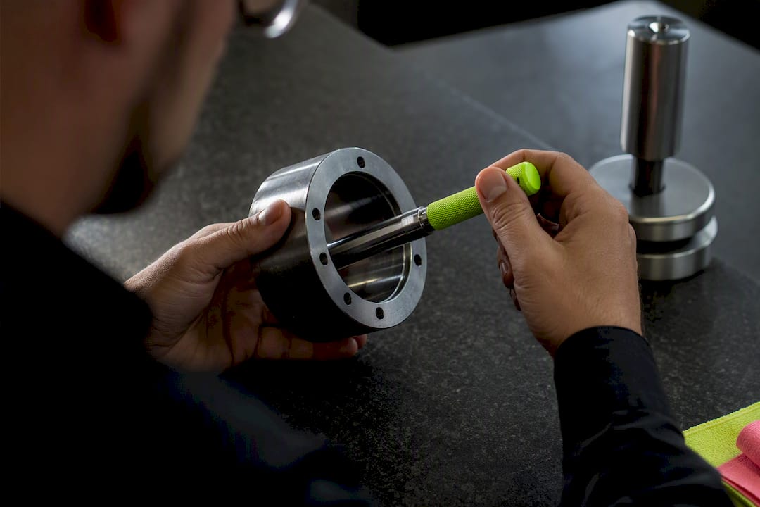
Use go/no-go gauges for production sampling, and add cylindricity or roundness checks on any bore where out-of-round error could eat into your calculated interference. A first-article inspection pass should confirm finish, chamfer geometry, concentricity, and an actual interference measurement before the run continues.
The Flying Chip Factory Take on Press Fit Tolerances
Fit tables get you most of the way there, but the last ten percent of a reliable press fit comes from shop feedback, not the standard. Flying Chip Factory builds tight-tolerance motorcycle hardware where a loose fit means a rattling part on a trail, and that work has reinforced one habit: talk to the machinist before the fit class is locked, not after the first parts come off the machine.
Which feature gets the tighter tolerance should depend on what your equipment actually holds well, and that answer changes shop to shop. Early conversation catches that mismatch before it becomes scrap.
— Drake
Get Precision-Fit Parts Machined Right the First Time
Fit tables and Lamé's equations get you close, but confirming a press fit actually works means holding tolerance on real parts and testing the assembly. Flying Chip Factory runs CNC prototyping and short-run production out of Athens, Alabama, with direct access to the machinist doing the work, so tolerance questions get answered in a phone call instead of a support ticket.

That direct line matters most when you're chasing a specific interference band. Flying Chip Factory offers precision boring and reaming, shaft turning and grinding, controlled surface finish work, and first-article inspection to confirm the fit before a full run starts. If a design needs a quick assembly trial to validate a fit class before committing to production quantities, that's a normal part of the process, not a change order. Request a quote or reach out directly to talk through your tolerance requirements before you cut the first part.
Sources
For deeper reference beyond this guide, consult ISO 286 and ANSI B4.1 for fit tables, DIN 7190 for elastic-plastic interference calculations, and an ISO fit calculator for quick limit-dimension lookups. Cross-reference flatness and parallelism requirements for any press-fit bore where roundness affects the final interference.
- Press Fit Tolerance: How to Specify Interference Fits
- Press Fit Tolerance: Charts, Fit Classes and DFM Guide