
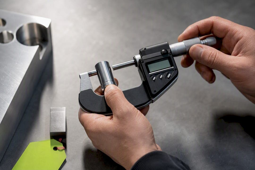
MMC is the material condition with the most material on a feature; LMC is the condition with the least. MMC grants bonus tolerance as a feature's actual size departs from its maximum material limit toward LMC, so pins get looser position tolerance as they shrink and holes get looser as they grow. Designers specify MMC when assembly clearance matters most, and LMC when a minimum wall thickness or a tight locational fit is the real risk. Both concepts are governed by ASME Y14.5, and getting the direction of the math backward is a common GD&T inspection error in shops like ours.
TL;DR:
- Bonus tolerance increases as parts depart from MMC toward LMC, but only if the feature is controlled and the size runs correctly for internal or external features.
- MMC for external features is the largest size, while for internal features it is the smallest size, affecting how bonus tolerance grows.
- Selecting MMC is ideal for assembly clearance, whereas choosing LMC protects minimum wall thickness or tight fit conditions.
- CMM software typically calculates bonus tolerance automatically, but inspectors should verify the math manually for accuracy.
- Proper understanding of datum shift versus bonus tolerance prevents frequent inspection errors related to contradictory or misapplied GD&T symbols.
MMC vs LMC: Symbols, Rules, and Which Way Size Runs
The circled M (Ⓜ) means maximum material condition. The circled L (Ⓛ) means least material condition. Neither symbol appears unless the drawing calls it out, because RFS is the default in GD&T, and RFS awards no bonus tolerance at all. That default trips up a lot of new CAD drafters who assume every position callout floats with size.
Here's where people get confused: MMC doesn't mean "the biggest number" in some universal sense. It means the condition with the most material, and that flips depending on whether you're looking at an external or internal feature.
- External features (pins, bosses, shafts): MMC is the largest allowed size. More material sticking out means more material.
- Internal features (holes, slots): MMC is the smallest allowed size. A smaller hole leaves more material in the part.
- LMC is the mirror image in both cases: the smallest pin, the largest hole.
- RFS applies regardless of actual size, unless Ⓜ or Ⓛ is explicitly noted in the feature control frame.
That reversal between pins and holes is the single most important thing to internalize before you touch the math, because it determines which direction bonus tolerance grows as parts come off the machine.
How Do You Calculate Bonus Tolerance?
Bonus tolerance is the numeric gap between a feature's actual measured size and its specified material condition, and it gets added directly to the geometric tolerance in the feature control frame. At exactly MMC, bonus tolerance is zero. As the part departs from MMC toward LMC, bonus tolerance grows by the exact amount of that departure.
Follow this sequence on any inspection report:
- Identify the feature's specified MMC and LMC size limits from the drawing.
- Measure the actual feature size with a CMM or gauge.
- Subtract to find the departure: for a pin, MMC minus actual size; for a hole, actual size minus MMC.
- Add that departure to the position tolerance stated at MMC in the feature control frame.
- Compare the result against the measured position error to accept or reject the part.
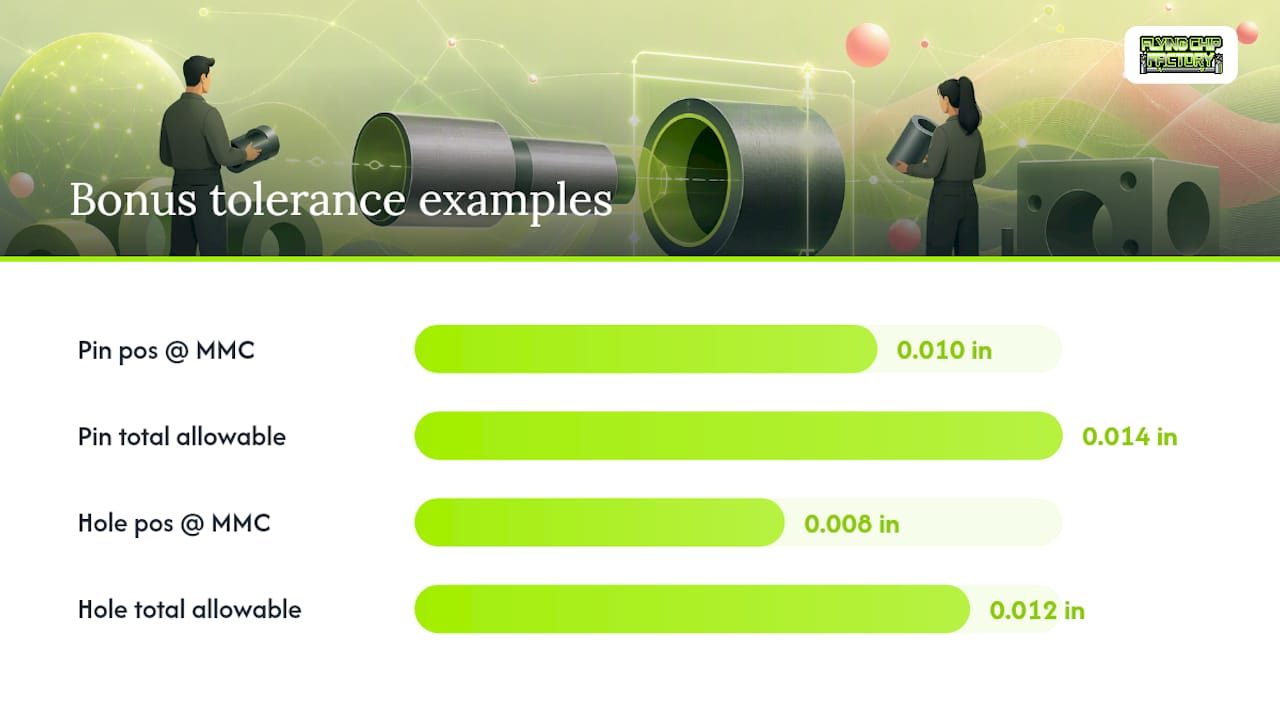
Worked example, external pin. Say a pin is specified at Ø0.500 MMC, Ø0.492 LMC, with position tolerance of 0.010 at MMC. A pin measuring Ø0.496 has departed 0.004 from MMC, so it earns 0.004 bonus tolerance, for a total allowable position tolerance of 0.014.
| Parameter | Value |
|---|---|
| MMC (largest pin) | Ø0.500 |
| LMC (smallest pin) | Ø0.492 |
| Position tolerance at MMC | 0.010 |
| Measured size | Ø0.496 |
| Bonus tolerance | 0.004 |
| Total allowable position tolerance | 0.014 |
Worked example, internal hole. A hole specified at Ø0.750 MMC, Ø0.758 LMC, with position tolerance of 0.008 at MMC, measures Ø0.754. The hole departed 0.004 past MMC (in the growing direction this time), earning the same 0.004 bonus and a total of 0.012.
Most CMM software, including PC-DMIS, calculates this automatically once you enter the feature's size limits, but every inspector on your floor should be able to reproduce the arithmetic by hand. If the software's bonus number doesn't match your own calculation, trust the manual check first.
What Is the Difference Between MMB/LMB and Feature MMC/LMC?
Maximum material boundary and least material boundary look like the same symbols applied to a different location on the drawing, but they do something entirely different. MMB and LMB modify datum features, not controlled features, and they change how the datum simulator contacts the part rather than changing any tolerance value_and_Least_Material_Boundary_(LMB).htm).
- Bonus tolerance loosens the allowable geometric variation of the controlled feature itself.
- Datum shift lets the entire datum reference frame float, translate, or rotate relative to the part when the datum feature departs from its specified boundary.
- Applying MMB to a datum feature does not add one thousandth to the tolerance of the hole or pin being positioned. It only changes how much the simulated datum can move.
- Complex fixtures sometimes combine translation modifiers with MMB/LMB to control which degrees of freedom the datum reference frame is allowed to use, which matters on multi-datum fixtures with stacked tolerances.
Pro Tip: When you're reviewing a CMM report, ask whether the number in question came from the controlled feature's size departure or from a datum feature's boundary condition. If it's the second one, it's datum shift, and it has no business showing up in your bonus tolerance column.
MMC or LMC: Which One Fits Your Design Intent?
MMC and LMC aren't interchangeable defaults. You pick one based on what actually breaks the part if size drifts.
Reach for MMC when the functional requirement is assembly clearance. Bolt patterns, dowel pin locations, and anything that has to slide together at final assembly benefit from bonus tolerance that loosens as parts shrink toward their minimum material state. MMC guarantees fit under worst-case material conditions while cutting unnecessary rejections on parts that are still perfectly assemblable.
Reach for LMC when the risk runs the other direction: minimum wall thickness, minimum edge distance, or a press fit where too little material causes a functional failure, not too much. LMC lets tolerance loosen as the part grows toward maximum material, protecting the thin-wall or tight-fit condition instead.
Run this three-question check before locking in a modifier:
- Does the feature need to clear another part, or does it need to retain enough material for strength or fit?
- What actual failure mode worries you more: interference (favor LMC) or looseness (favor MMC)?
- Is this the datum feature or the controlled feature? Only one material condition ever applies to a given feature at a time, since specifying both MMC and LMC on the same feature creates a conflicting requirement.
How Do Shops Verify MMC and LMC on the Floor?
Functional go/no-go gauges are built to the worst-case boundary, meaning a pin gauge sized to a hole's virtual condition (MMC size combined with the stated geometric tolerance) either passes or it doesn't. That single pass/fail check silently verifies both size and position at once, without a single measurement number.
- A go gauge that fits confirms the hole meets both size and position limits at its worst-case boundary.
- CMM software computes bonus tolerance from measured size, then adds it to the position tolerance automatically. PTC Creo and similar packages expose the boundary values directly so inspectors aren't guessing at the math.
- Report the actual measured size alongside the calculated bonus tolerance on every sheet, not just the pass/fail result.
- Flag any part measured exactly at RFS-style zero bonus separately, since that's where false rejects cluster if a technician forgets to apply the modifier.
- Cross-check dowel and locating pin fits against a spec-ready pin and hole tolerance reference before signing off a first-run inspection report.
Common MMC/LMC Mistakes and How to Catch Them
Most inspection errors trace back to one of a handful of repeat offenders, and every one of them is catchable on a five-minute drawing review.
- Treating datum shift as bonus tolerance and adding it to the feature's position tolerance twice.
- Applying both Ⓜ and Ⓛ to the same feature, which produces a conflicting, unbuildable requirement.
- Misreading which direction size runs on an internal feature, since MMC on a hole is the smallest size, not the largest.
- Forgetting that RFS is the default and assuming bonus tolerance applies when no modifier is actually printed on the drawing.
Pro Tip: Keep a laminated symbol card at every CMM station. It sounds low tech, but a five-second glance at Ⓜ versus Ⓛ prevents more rework than any software update we've deployed.
How Flying Chip Factory Applies MMC/LMC in CNC Work
Flying Chip Factory's parts are developed by riders who also run the CNC machines, which means every kickstand and mount goes through the same size-versus-position tradeoffs covered above before it ever reaches a customer.
- Fixture design for short-run production often depends on whether a locating feature is called at MMC (clearance-driven) or RFS, since that decision changes how much play the fixture pins are allowed.
- Lap plate flatness checks feed directly into datum simulator accuracy, because a datum reference frame is only as good as the surface it's measured against.
- On prototype runs, direct access to the machinist means a bonus tolerance question gets answered in one conversation instead of a week of email.
Where to Go Deeper on MMC and LMC
- ASME Y14.5 is the governing standard behind every symbol and rule discussed here.
- FARO's MMC and bonus tolerance explainer walks through animated 3D examples that make the size-versus-tolerance relationship easier to visualize.
- Xometry's MMC reference covers why MMC suits assembly-driven part families.
- Hexagon's PC-DMIS documentation on MMB/LMB breaks down datum boundary behavior in practical software terms.
- Tec-Ease's GD&T tips offer quick, shop-floor-tested corrections for common misreads.
Get CNC-Machined Parts Built Around the Right Tolerance Callout
Choosing between MMC and LMC isn't an academic exercise. It decides whether a fixture pin binds, whether a bolt pattern assembles on the first try, and whether your inspection report matches reality. If you're prototyping a bracket, fixture, or replacement part and need someone who actually reads the feature control frame before quoting the job, Flying Chip Factory machines prototypes and short runs with direct access to the machinist running your parts, so a tolerance question gets a same-day answer instead of a ticket number. Get a quote and talk through your drawing before the first cut, not after.
The Overrated Half of the MMC vs LMC Debate

Most explainers treat MMC and LMC as a symmetry problem, some interchangeable pair you memorize with a mnemonic and move on. That's backward. In practice, LMC shows up on a small fraction of real drawings compared to MMC, because most functional requirements in machined parts are assembly problems, not minimum-wall problems. The real skill worth building isn't memorizing which letter means what. It's recognizing, feature by feature, whether your part actually fails from too little material or too much clearance.
The conventional advice also underweights datum shift. Engineers spend hours mastering bonus tolerance arithmetic and then misapply the exact same logic to an MMB-modified datum, which is a different mechanism with a different failure mode. If you only fix one habit after reading this, fix that one: before you add any number to a position tolerance, ask whether it's coming from the feature's own size departure or from a datum simulator shifting underneath the whole part. Get that distinction right and the arithmetic takes care of itself.
— Drake