
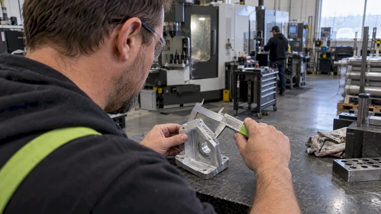
When a part has no drawings, pick the capture method by geometry: calipers or photo+AI for prismatic shapes with flat faces and round holes, 3D scanning for free-form or organic surfaces. Whatever method you choose, the workflow runs through three phases, capture, model, and verify, and the single step that saves the most rework is anchoring your whole dataset to one trusted measurement while you confirm which features actually mate with something else.
TL;DR:
- Choosing the correct capture method depends on geometry complexity and accuracy needs, with calipers for simple prismatic parts and 3D scanning for organic surfaces.
- Anchor measurements taken with calipers or gauges serve as the only trusted reference point to calibrate and validate the entire reverse engineering process.
- Wear, corrosion, and manufacturing marks distort measured dimensions, so always interpret data as clues to design intent, not exact targets.
- Registering mesh data to datum features yields more reliable interchangeability than best-fit alignment, which can obscure real deviations.
- Final verification involves comparing the modeled CAD against the original scan, focusing on deviations that impact function or mating interfaces.
Why undocumented parts are a different engineering problem
Measuring a part and copying its numbers is not the same as understanding why it was built that way. A worn bushing bore, a chewed-up keyway, or a corroded flange face will hand you numbers that reflect years of use, not the design intent behind them. Reverse engineering defined this way, as recreating design data from a physical object, runs through three phases: information extraction, modeling, and review according to Wikipedia's overview of reverse engineering. Skipping the review phase is where most shop drawings go wrong.
A few things make undocumented parts genuinely harder than a normal design job:
- As-measured dimensions are not design intent. Wear, corrosion, and thermal cycling push real numbers away from the originals.
- Mating features and their tolerances, not raw dimensions, determine whether a replacement part actually fits.
- Material grade, surface treatment, and the original manufacturing method all affect how a copy performs under load, not just how it looks.
Treat every measurement as a clue about intent rather than a target to hit exactly.
Plan the capture: method selection, datums, and anchor measurement
Before you touch a part with a caliper or a scanner, decide what level of accuracy the job actually needs. A bracket that bolts to a fixed hole pattern needs tight hole-to-hole tolerances. A cosmetic cover panel does not.
Three factors drive method choice: how complex the geometry is, how tight the required tolerance is, and how much time and budget you have. Flat, prismatic parts with machined faces are fast with calipers and a 3D CAD package. Free-form shapes, cast housings, or ergonomic grips need a 3D scanner to capture surface continuity that calipers cannot describe.
Work through the plan in this order:
- Identify the two to four features that matter most for fit: mating faces, hole patterns, shaft diameters, or bearing bores.
- Decide your datum scheme now, not after modeling, so every later measurement references the same origin and axes.
- Take one high-confidence reference dimension before any scan or photo session, ideally a feature you can measure with a caliper or gauge to a known accuracy.
- Note anything that looks worn, chipped, or out of round so you do not accidentally model damage as design geometry.
That reference dimension becomes your scale anchor for everything downstream, whether you are aligning a point cloud or calibrating a photograph.
Pro Tip: Measure your anchor dimension twice, with two different tools if you have them. A single bad caliper reading early in the process propagates into every feature you model from it.
Practical capture techniques: calipers, CMM, 3D scanning, and photo→CAD
Each capture method has a sweet spot, and mixing them on one part is common and often correct.
- Caliper and CAD: measure overall envelope dimensions, hole diameters and spacing, wall thicknesses, and fillet radii directly into a CAD sketch; the main pitfall is skipping features hidden behind other geometry, so measure inside pockets and counterbores separately.
- CMM: probe from a fixtured setup so every point references the same coordinate system; this matters most when hole patterns or bolt circles need to interchange with a mating part.
- 3D scanning: plan overlapping passes so every surface gets covered from at least two angles, use physical or printed markers for registration, and rescan reflective or dark surfaces with a dulling spray if the scanner struggles.
- Photo plus AI: shoot the part from orthographic-style angles with consistent lighting, include a ruler or known-size object in frame, then anchor the output to your one trusted measurement before exporting.
Method choice should scale with geometry and accuracy needs: manual caliper measurement suits simple prismatic parts, while advanced 3D scanning is better suited to complex free-form surfaces, a split confirmed by Wikipedia's reverse engineering entry. For many shop-floor parts, a photo-plus-AI approach anchored to a single real measurement can produce a dimensioned, exportable drawing quickly, with 3D scanning reserved for organic or highly curved shapes, according to TechDraw AI's guidance on reverse engineering without drawings. Whichever method you use, the anchor measurement is what turns raw capture data into something you can trust for manufacturing.
Mesh and point-cloud processing: cleanup and registration
Raw scan data is never ready to model from directly. It carries noise, gaps, and artifacts that need careful handling, especially around features that mate with something else.
- Remove outlier points and fill small holes conservatively, favoring the surrounding surface trend over aggressive smoothing.
- Preserve mating surfaces exactly as scanned; these are the last places you want automatic hole-filling or smoothing algorithms to touch.
- Register the mesh by datum features, not by overall best-fit, whenever the part needs to interchange with another component.
- Reserve best-fit alignment for surfaces that do not locate anything, like a cosmetic cover or a non-functional rib.
- Simplify mesh density where manufacturability requires a lighter file, but never simplify through a functional radius or a bearing seat.
Datum-based registration matters most during verification: contactless measurement guidance recommends anchoring inspection data to datum features and limiting best-fit alignment to non-locating surfaces, which keeps interchangeability intact rather than papering over real deviations. Over-smoothing is the most common mistake at this stage. It makes a mesh look clean in a viewer while quietly erasing the sharp edge or step that a mating part actually needs to register against.
Judging wear, damage, material, and manufacturing features vs original design
The hardest judgment call in reverse engineering is separating what the designer intended from what twenty years of service did to the part. Start by hunting for unworn reference regions: a bore's unworn end, a thread's root diameter, or a surface protected under a gasket. These regions often reveal the original nominal size far better than the worn, exposed areas.

Once you have a candidate dimension, round it to the nearest standard value before trusting it. A practitioner heuristic worth following: prefer a nominal size like 12.00 millimeters over a worn measurement like 11.97 millimeters when wear is evident, since designers almost always specify standard increments, as noted in TechDraw AI's mechanical reverse-engineering workflow guide.
Material identification matters just as much as geometry for anything load-bearing. A magnet test separates ferrous from non-ferrous alloys in seconds. A hardness spot check with a file or portable tester narrows down heat treatment state. XRF analysis is worth the cost when the application is dynamic or safety-critical and you need a confirmed alloy grade rather than a guess.
Toolmarks, parting lines, and draft angles are free information about how the original part was made, whether it was cast, forged, machined, or molded, and that manufacturing signature should guide your own process selection later.
Reconstructing functional intent, mating interfaces, and tolerance strategy
Measured geometry only becomes a usable design once you decide which features actually control fit and function. Start by identifying the critical-to-function features: bearing bores, hole patterns that bolt to something else, shaft diameters inside a bushing, sealing faces. These features get your tightest tolerance budget. Everything else, cosmetic ribs, draft surfaces, non-mating walls, can carry looser general tolerances without risk.
- Build a datum hierarchy before you dimension anything, then apply GD&T callouts per ASME Y14.5 for location and orientation rather than relying on plus-or-minus dimensions alone.
- Decide fit type deliberately: a running clearance fit, a press fit, or a locational fit each call for different tolerance classes, and guessing here is how parts bind or rattle in service.
- Reserve tight custom tolerances for features that genuinely need them; standard tolerance blocks are cheaper to machine and just as reliable for non-critical surfaces.
Separating measured geometry from design intent is the step most reverse-engineering guides flag as the real difference between a part that fits and one that does not, and the practice of checking unworn mating surfaces before settling on nominal values is explicitly recommended in TechDraw AI's reverse-engineering blog. Hole-to-hole location tolerance and dowel pin fits deserve particular attention if the part needs to bolt to a fixture or mate with another assembly; a dedicated reference on dowel pin hole tolerances covers the practical ranges shops use. Flatness and parallelism callouts also get confused often enough that it is worth reviewing the difference between flatness and parallelism before you finalize a sealing face tolerance.
Build editable parametric CAD: scan-to-CAD best practices
A mesh or point cloud is not a usable engineering model until it becomes parametric, editable, and dimensioned around real design logic rather than thousands of individual points.
- Decide which geometry needs full parametric control: function-critical features like bores, bosses, and mounting patterns get modeled as true sketches and features.
- Treat purely cosmetic or non-mating surfaces as reference geometry, imported or wrapped around the mesh rather than hand-rebuilt feature by feature.
- Use symmetry and your anchor datums to rebuild features cleanly: a part with a mirrored bolt pattern only needs one side measured precisely if you can confirm the symmetry holds.
- Cross-check every rebuilt feature against the original mesh with a deviation check before moving to the next feature.
- Export the finished model as STEP, IGES, or Parasolid for any part headed to a CNC shop, since these formats preserve exact surfaces and editable history that a machinist's CAM software can work with directly.
Pro Tip: Send STEP, not STL, when you want a CNC quote. STL files approximate curves with flat triangles and strip out the parametric data a machinist needs, which is a common cause of a week of back-and-forth clarification requests, a pattern discussed in the STL versus STEP comparison for CNC work.
STL remains the right call when the end use is additive manufacturing or a visual prototype where exact parametric control does not matter. For anything going to a machine shop, the parametric STEP file is what lets a machinist adjust a hole size or add a chamfer without rebuilding your whole model. An academic comparison of reverse-engineering methodologies across different starting inputs, paper drawings, physical parts, and existing 3D models, found consistent trade-offs in time and accuracy depending on the chosen path, reinforcing that the scan-to-CAD route works best when paired with deliberate measurement planning rather than scanning first and figuring out the model later, according to an Aalto University thesis on reverse-engineering methods for spare parts. A full walkthrough of the scan-to-CAD process, including tooling choices, is covered in a practical scan-to-CAD workflow guide.
Verification and validation: scan-vs-model checks and production readiness
A reconstructed model is a guess until you check it against the physical part with objective data, not a visual once-over.
- Run a deviation map comparing your finished CAD model back against the original scan or point cloud, and flag any area that exceeds your tolerance budget.
- Separate deviations that affect function from ones that do not; a 0.1 millimeter deviation on a cosmetic rib is irrelevant, the same deviation on a bearing bore is not.
- Build an inspection checklist covering every critical-to-function dimension, every mating interface, and surface finish on sealing or sliding surfaces.
- Use go/no-go gauges on critical hole patterns and shafts before committing to a full production run.
- Run a small test assembly or sample batch to catch integration problems that a single part check would miss.
Using 3D scanning paired with deviation analysis for verification, rather than relying on traditional spot-check measurement alone, has been shown to catch geometric deviations that improve fixture and production quality on complex assemblies, according to an applied study on verifying geometrically complex components. Observational research into how practitioners actually work found that the process is rarely one straight pass. Engineers move between an overview phase, focused sub-component scanning, and targeted testing, letting experience guide where extra scrutiny is worth the time, a pattern documented in a USENIX observational study of reverse-engineering practices. Build that iteration into your own schedule rather than assuming one scan and one model pass will be enough.
Shop-tested tips and Flying Chip Factory workflow examples
A few habits consistently cut the number of clarification rounds on a reverse-engineering job. Choosing a datum scheme that mirrors how the part actually mounts, rather than an arbitrary corner, avoids most of the back-and-forth; the logic behind that choice is covered in a reference on true-position basics for prototype shops. Direct contact with the machinist running the job matters just as much as the drawing itself: a quick phone call about a borderline tolerance call resolves in minutes what an email chain would stretch into days.
Not every reverse-engineered part should be an exact copy. A bracket that cracked from fatigue might be a better candidate for a material upgrade or a heat treatment change than a geometric clone of the original failure. Some in-house parts follow the logic that function and fit come first, with material choices reconsidered when the original design clearly had room to improve.

A shop floor perspective on reverse engineering priorities
Most reverse-engineering writeups treat the drawing as the finish line. On the shop floor, the drawing is just the halfway point. I care about function first: does this feature actually need to be tight, or did someone just measure what was in front of them. Manufacturability comes second, because a perfect digital twin of a part that is expensive or slow to machine helps nobody. Exact dimensional fidelity comes third, and only where it genuinely matters, since copying a worn part's exact wear pattern is often the wrong goal entirely.
— Drake
How Flying Chip Factory turns reverse-engineered data into finished parts

Once you have a manufacturing-ready model, the next step is selecting a partner skilled in fabrication; learn more about how to choose a metal shop in our guide to selecting a metal fabricator for precise industrial projects. Prototype machining, short-run production, and fixture, bracket, and support part fabrication can be run from a single shop with direct communication to the machinist actually running the job. That means a borderline tolerance call or a question about your anchor measurement gets answered directly, not relayed through three people. An example product started as exactly this kind of reverse-engineering problem: worn mounting points, no original drawings, and a functional fit that had to work on the first run. You can see the finished result on the E2 Kickstand product page. If your own reverse-engineered part needs a shop that will push back on a bad tolerance before it becomes a bad part, get a quote through our prototype and short-run machining services.
FAQ
Is reverse engineering illegal in the US?
Reverse engineering a physical part to understand or recreate its function is generally legal, though copying a part protected by an active patent, trademark, or exclusive design right can create legal exposure. The legality depends heavily on what is protected and how the resulting part is used, so check the specific intellectual property status of a part before producing it commercially.
Does engineering require drawing?
Traditional engineering relies heavily on drawings and CAD models to communicate design intent, tolerances, and manufacturing instructions. Reverse engineering without original drawings still ends in a drawing or CAD model, it is just built backward from the physical part through capture, modeling, and verification.
Will AI replace reverse engineering?
AI tools, particularly photo-to-CAD systems, already speed up parts of the process by generating dimensioned drawings from photographs anchored to one real measurement, as described in TechDraw AI's guidance on reverse engineering without drawings. They do not replace the engineering judgment needed to separate wear from design intent or to set tolerances for mating features, which still requires a person who understands how the part functions.
What are the different types of reverse engineering?
Capture methods generally fall into manual measurement with calipers or a CMM, 3D scanning for complex or free-form surfaces, and photo-based capture assisted by AI for quick, anchored drawings. Method choice depends on geometry complexity, required tolerance, and how fast the result is needed, with manual measurement suited to simple prismatic parts and scanning reserved for organic shapes.
Sources
- Reverse engineering — Wikipedia
- How do I reverse engineer a part with no drawings? | TechDraw AI
- Observational study of reverse-engineering practices — USENIX
- Methods to reverse engineer spare parts — Aalto University thesis (E. Colombo)