
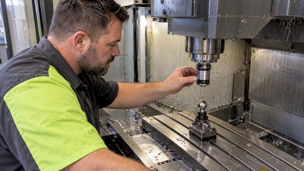
On-machine probing uses a spindle-mounted probe to measure and control part and tool geometry right on the machine, speeding setup and enabling in-process checks. It cuts manual alignment time, catches tool wear before it ruins a part, and supports lights-out runs. The tradeoff is environmental: shop temperature swings and machine wear limit how much you can trust it without validation against a traceable reference.
TL;DR:
- Use touch trigger probes for point checks and offsets; choose strain gage probes for continuous scanning, and use the shortest stylus that reaches the feature.
- Calibrate against a known artifact, validate the first part with a calibrated reference, and recalibrate after stylus changes, collisions, drops, or major temperature shifts.
- Match calibration speed to the programmed probing feed rate; controller timing delays can distort readings at high speeds, while stylus length and approach direction cause lobing.
- Program safe approach and retract paths, clean chip covered surfaces, and define an alarm, retry, or stop response for any failed probe trip.
- Use on machine checks for process control, but send critical parts to a coordinate measuring machine for final certification and documented traceability.
Core functions and use cases of on-machine probing
Probing earns its keep across the whole job, not just at setup. The most common application is establishing work offsets: instead of an operator indicating a fixture by hand, a probe cycle finds the part's edges or bores and sets the coordinate system in seconds.
From there, the uses stack up:
- Pre-process checks confirm the raw stock is present, clamped correctly, and sitting where the program expects.
- In-process monitoring flags tool wear or breakage mid-cycle, before a damaged tool scraps the next ten features.
- Post-process inspection gives a quick GO/NO-GO read on critical dimensions without pulling the part to a gauge station.
- Tool setting measures length and radius at the spindle and updates offsets automatically, which matters most when running multiple tools through a long unattended cycle.
Each of these can run independently or chained together in one program. A shop running small-batch prototype work might only need work offsets and tool setting, while a lights-out night shift leans on in-process and post-process checks to keep running without an operator present.
Choosing probe hardware, styli, and signal systems
Touch-trigger probes dominate shop-floor use because they are simple, durable, and accurate enough for most tolerance bands. Strain-gage probes offer better repeatability on fine-feature scanning but cost more and see less use outside dedicated metrology cells, according to the mechanics described in Cutting Tool Engineering's probing primer.
A few hardware choices shape results more than people expect:
- Touch-trigger vs strain-gage: touch-trigger suits point measurement and offset setting; strain-gage suits continuous scanning.
- Wireless vs cable-bound activation: wireless probes simplify tool-change routines but need battery and signal checks built into your maintenance routine.
- Stylus geometry: shorter styli reduce deflection and lobing error, while longer or right-angle styli trade accuracy for reach into pockets and bores.
- Accessory features: integrated cleaning, collision-detect adapters, and thermal decouplers protect repeatability in dirty or hot environments, as HEIDENHAIN's touch probe brochure notes.
Pro Tip: Keep a dedicated short stylus for your most common bore and edge-find cycles, and reserve longer styli only for features nothing else can reach.
Calibration, validation, and traceability best practices
A probe is only as good as its last calibration. Vendor guidance from Renishaw's machine tool probe calibration guide?userLanguage=en) lays out a repeatable sequence that most shops can adapt directly.
- Calibrate against a known artifact. Use a ring gauge, sphere, or test bar to establish electronic probe length and stylus ball radius.
- Validate the first part. Compare the probe's reading on an early production part against a calibrated reference device before trusting the cycle for the rest of the run.
- Run the standard test battery. Stylus tip offset checks, repeatability tests, and 2D or 3D probing error tests confirm the system performs within spec; NEN-ISO 230-10 defines the test methods shops reference for this.
- Recalibrate on trigger events. A stylus change, a collision or drop, or a significant shop temperature shift all call for a fresh calibration, not a wait-and-see approach.
Traceability matters more as tolerances tighten. For parts headed into a formal quality record, pairing on-machine checks with documented first-part validation closes the gap between a quick shop-floor check and a defensible measurement. Shops that want outside calibration support can also look at accredited calibration providers, such as the scheduling guidance in PCS Precision's calibration overview, to keep reference artifacts themselves within certification.
Programming and CAM workflow for on-machine probing
Probing cycles sit at specific points in the program flow: before machining to set offsets, between operations to check tool condition, and after machining to confirm the result. CAM packages like Siemens NX generate these probing paths directly from the part model, which keeps the probe moves synchronized with the same geometry the cutting tools use.
Typical cycles you will program on a regular basis:
- Corner find and edge find for establishing XY zero on a fixture or raw stock.
- Bore or boss center find for locating a feature's true center before a finish pass.
- Circle fit across multiple points for a more robust center and diameter read than a two-point check.
- Single-point feature checks for quick confirmation of a critical dimension mid-program.
Measured values feed back into work offsets and tool offsets automatically, and on more advanced setups, into adaptive machining loops that adjust feeds or depths based on what the probe finds. Keep approach vectors perpendicular to the surface where possible, orient the spindle consistently between cycles, and build in enough retract clearance to clear clamps and fixture plates. Always program a defined response for a bad trip, whether that is an alarm, a retry, or a program halt, rather than letting the cycle continue on a false read.
Probing speed, timing errors, and accuracy limits
Probing is not free of error just because it happens on the machine. Controller timing introduces a lag between the physical trigger and the recorded position, and that lag grows with feed rate.
NIST testing found timing delays at very high probing feed rates, and recommends calibrating with gauge blocks or spheres at the feed rate you actually plan to run, according to NIST IR 6415. Running faster than your calibration feed rate without re-validating introduces exactly the kind of silent error that shows up as a bad part three operations later.
Stylus length and approach direction add their own variation, a pattern known as probe lobing, where the recorded trigger point shifts slightly depending on which direction the stylus approaches from. Vendor-recommended speeds are a starting point, not a guarantee. Building a simple error budget that accounts for probe repeatability, stylus deflection, machine geometric error, and thermal drift gives you a realistic picture of whether on-machine measurement is tight enough for a given feature, or whether it needs a follow-up check on a CMM.

Practical implementation checklist and common pitfalls
Getting on-machine probing running reliably comes down to a short list of habits done consistently.
- Before programming: pick the right probe and stylus for the job, mount a calibration artifact securely, and define what you actually need to measure.
- While programming: build in clean probe activation, safe approach paths, a consistent spindle orientation, and a cleaning pass before any touch-off on a dirty part.
- During operation: validate the first part against a reference, follow a stylus-change protocol every time hardware changes, and keep calibration on a set schedule rather than an as-needed basis.
Pro Tip: Treat a skipped first-part validation as a red flag, not a shortcut, since most probing failures trace back to that step being skipped under schedule pressure.
The recurring mistakes are predictable: probing off a chip-covered surface, running a stylus longer than the feature actually requires, and skipping feed-rate-specific calibration after bumping up cycle speed to save time.
Shop-floor tips from Flying Chip Factory
On prototype work, we default to the shortest stylus that reaches the feature, since it cuts deflection error on parts where we rarely get a second cut at the fixture. Stable, repeatable fixture referencing has saved real iteration time on short-run jobs where a part comes back for a quick revision. When a customer needs help with fixture design, probe-ready setups, or a second look at a probing program, we discuss it directly.
When on-machine probing earns its place
On-machine probing pays off fastest on tight-tolerance features, costly materials, and lights-out runs where a bad part means real loss. A CMM still wins for final certification and the highest traceability. Pilot probing on a low-risk part before rolling it into your main process.
— Drake
Probe-ready machining and prototyping with Flying Chip Factory
We build parts with probing in mind from the first design pass, whether that means a prototype that needs quick iteration or a short production run with fixtures sized for repeatable referencing. Our prototype machining and short-run production services cover fixtures, brackets, and support parts, and every job runs through direct communication with the machinist who builds it. If you ride electric mini dirt bikes, our E2 Kickstand is a bolt-on part machined the same way. Reach out for a quote or a quick technical conversation about your next job.

FAQ
What measuring instruments are needed for CNC machines?
A CNC shop typically pairs a spindle-mounted touch-trigger probe for in-machine checks with calibration artifacts like ring gauges, spheres, and test bars. Many shops also keep a CMM or handheld gauges on hand for final verification of critical features.
What is probe measurement?
Probe measurement is the process of using a physical stylus to contact a surface and record its position, which the control then uses to calculate offsets or dimensions. On a machine tool, this happens through a touch-trigger or strain-gage probe mounted in the spindle.
What are the 7 major parts of a CNC machine?
A CNC machine generally consists of the machine bed, spindle, tool changer, axis drive motors, control unit, coolant system, and the worktable or fixture plate that holds the part. Exact configurations vary by machine type and manufacturer.
How does the touch trigger probe function?
A touch-trigger probe contains a mechanism that generates a signal the instant the stylus contacts a surface, which the machine control uses to record the axis position at that moment. Mechanical design in these probes can introduce direction-dependent variation known as lobing, according to Cutting Tool Engineering.
Sources
- NIST IR 6415 — Fast probing considerations for on-machine inspection
- HEIDENHAIN — Touch probes product brochure
- Cutting Tool Engineering — The basics of on-machine probing