
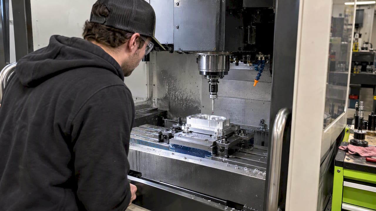
For a CNC-machined prototype, run dimensional inspection (CMM, on-machine probing or optical), mechanical and fatigue testing including accelerated vibration, functional fit checks, and environmental screening. Pick by the biggest risk: tolerance points to metrology, load and life point to fatigue rigs, environment points to screening, and iteration speed points to on-machine probing. We lean on ISO 14253-1 and NIST work, and we machine prototypes in Athens, Alabama.
TL;DR:
- Conventional servohydraulic fatigue tests run at 0.25 to 10 Hz, while resonant vibration methods can produce cycle counts tens of times faster.
- For measurements near tolerance limits, include uncertainty and apply ISO 14253 Part 1 (2017) decision rules; a near limit reading is not automatically a pass.
- Calibrate probes at the operating feed rate, compensate for effective tip radius, and send features near the limit to a CMM or optical lab.
- Define pass or fail criteria from the intended application before testing, and document the method, sample size, measurement resolution, fixture, and raw results.
- Use coupons to characterize material and process, but test full scale components when geometry, fixtures, or combined loads could drive failure.
1. Which test categories cover a physical prototype?
Several categories handle nearly every CNC prototype. Knowing which one fits your risk saves days of testing the wrong thing.
- Dimensional and metrology: a CMM check of a bore pattern against the drawing.
- Mechanical and fatigue: cycling a bracket at its working load until it cracks or survives.
- Functional and fit: bolting the part onto its mating assembly and checking clearance, torque and motion.
- Environmental and durability: heat, cold, vibration and shock, scaled to the real service conditions. Spaceflight programs run vibration, shock and thermal vacuum tests, and the same logic can be scaled down for industrial parts.
- NDE and visual screening: dye penetrant or magnified inspection for cracks and machining defects.
Stop at simple checks when the part is a form-and-fit mockup. Move to formal characterization when failure would hurt someone or when you need life data.
2. How do you trust dimensional results from a CMM or probe?
Touch-probe measurement is well understood, but the main error sources are probe tip size and triggering sensitivity. NIST's survey of dimensional metrology groups methods into touch probes, optical techniques such as confocal and fringe projection, and scanning probe microscopy. Choose by feature access: optical methods suit fragile parts or high point counts, while a touch probe suits bores and datums.
Apply the gage-maker's rule: your measurement system should comfortably beat the part tolerance. If your measurement system is only as precise as the tolerance you are machining to, you cannot reliably distinguish good parts from marginal ones. Tighter tolerances raise this burden, which is why our tight-tolerance machining guide pairs every tolerance call with an inspection plan.
- Validate the probe radius compensation before trusting absolute dimensions.
- Confirm your CMM software's fitting algorithms against reference data, since NIST publishes algorithm test sets for least-squares fits.
- When a result sits near a spec limit, apply the decision rules in ISO 14253-1:2017, which covers how measurement uncertainty affects conformity calls.
Pro Tip: Write the measurement uncertainty next to every near-limit result. A reading close to the limit, when measurement uncertainty could put it outside the limit, is not a clear pass.
3. How do fatigue and accelerated vibration tests work?
Traditional servohydraulic fatigue testing typically runs at 0.25 Hz to 10 Hz, often across dozens of specimens at different amplitudes. That is slow. Vibration-based methods excite resonance near kilohertz frequencies, so S–N data that takes days on a load frame arrives in hours.
Accelerated vibration rigs cut test time dramatically: a resonant cantilevered plate near 1600 Hz reaches cycle counts tens of times faster than axial load frames.
- Carrier-insert designs hold specimens on a shaker-driven carrier so setup is reusable.
- Dual-resonant assemblies alternate modes to load two specimens in turn; a two-specimen vibration assembly can improve throughput compared with sequential testing.
- Instrumentation: strain gauges, and digital image correlation when you need full-field strain. Correlate specimen strain to shaker velocity so you can control the test in real time.
- Coupon versus component: use coupons to characterize material and process, and full-scale rigs when geometry, fixtures or combined loads drive the failure. Turbine programs even run combined low and high cycle tests on full-scale parts for that reason.
For a motorcycle component such as a kickstand, add riding-condition loading and material checks like hardness and tensile strength to the mix.
4. How does on-machine inspection speed up iteration?
Process-intermittent gauging means probing between cuts, so measured data can drive an immediate toolpath adjustment instead of waiting for a CMM slot. The catch is feed rate. NIST research on fast probing shows a time delay between probe contact and recorded machine position, and higher feed rates raise the effective probe error. A Real-Time Error Corrector (RTEC) latches axis positions at the instant of the trigger, which allows faster probing without that lag.
- Calibrate the probe at the exact feed rate you will use.
- Measure the effective tip radius at that rate and apply it as a compensation.
- Probe critical features between roughing and finishing cuts.
- Update offsets or toolpaths from the data.
- Send parts to a CMM or optical lab when tolerances approach your probe's repeatability.
We walk through the setup in our on-machine probing calibration steps.
Pro Tip: Record the feed rate and compensation value with every probing program. Without them, a later run cannot be compared to the first.

5. How do you build a prototype test plan with accept/reject criteria?
Start from the intended application and required function, then set accept/reject criteria before any test runs. Failing to tie criteria to the application is a classic error when time and cost rule out full characterization and qualification has to carry the validation.
- Objective: what the part must do, and the load, life or fit that proves it.
- Method and sample size: larger N for characterization, a statistical plan for qualification. NASA's parts program treats screening, characterization and qualification as separate steps with pass/fail tied to earlier results.
- Measurement resolution: map each test to equipment good enough to resolve the tolerance.
- Setup and fixture: photos, torque values, fixture IDs.
- Decision rule: the ISO 14253-1 treatment of uncertainty.
- Report: objective, setup, tools, pass/fail criteria, raw data snapshot, conclusion.
Our first article inspection guide shows a ready-made report layout.
6. What shop habits reduce rework?
- Calibrate probes for the feed rate you will use and write down the compensation.
- Build reusable fixtures or carrier inserts so fatigue specimens go in quickly.
- Run a quick gage R&R or SPC check before trusting pass/fail calls; our SPC guidance for prototype machining covers the routine.
- Log setup differences between iterations so root causes stay traceable.
- Check that your CAD's tolerancing survives into inspection data; NIST's GD&T test cases help catch surprises.
- Control test-rig error too: a runout compensator reduced life-cycle uncertainty in drilling-tool fatigue tests.
Pro Tip: Change one variable per iteration. If you alter the fixture and the toolpath together, you will not know which one moved the result.
7. Where I land on speed versus confidence
I run the smallest test set that proves the prototype does its job, and I decide the pass/fail line before the first cut. Measurement uncertainty is part of the decision, not a footnote. Escalate to formal lab work when life, safety or regulation is on the line. Simulation helps, but physical validation still has to confirm it, as integrated modeling research makes clear. An experienced shop that builds fixtures and machines iterations shortens the loop.
— Drake
8. How we support prototype testing and short-run validation
We machine prototypes, short runs and fixtures in one shop, and you talk directly to the machinist who builds your parts, so revisions move fast. Reach out through our prototype machining page for:
- On-machine probing calibration and setup
- First-article inspection support
- Short-run test-fixture builds and validation runs
Our E2 Kickstand shows the kind of finished part we deliver. Send us your drawing and we will quote it.
FAQ
What are the main prototype testing methods?
The main methods are dimensional inspection, mechanical and fatigue testing, functional fit checks, environmental screening, and non-destructive evaluation. Pick them by your prototype's biggest risk: tolerance, load, life or environment.
How do you choose a test for a CNC prototype?
Match the test to the failure that worries you most. Fit problems call for dimensional checks, load and life questions call for fatigue testing, and harsh service conditions call for environmental screening.
How do you set accept/reject criteria?
Define them from the intended application before testing begins. For measurements near tolerance limits, apply the decision rules in ISO 14253-1:2017, which account for measurement uncertainty.
Why calibrate on-machine probing for feed rate?
A time delay between probe contact and the recorded position creates an effective probe-tip error that grows with feed rate. NIST experiments show a simple effective-radius compensation corrects it.