
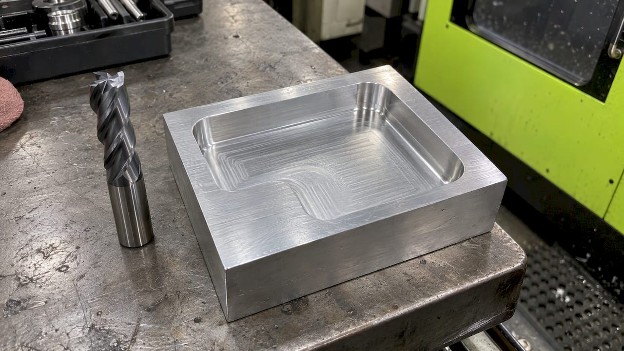
DFM for machining means shaping a part so a CNC mill or lathe can make it with standard tools, few setups and tolerances that match what the part actually does. Do that before release and the quote drops, the lead time shortens and the first article is more likely to be right. This guide covers the design choices that matter most, in the order we would check them.
TL;DR
- DFM for CNC is a design habit, not a late review: material, tool access, setups, tolerances and inspection are decided while the part is still a sketch.
- Check geometry first (internal radii, wall thickness, pocket depth, hole sizes), because no tolerance note rescues a part that flexes or chatters.
- Put tight tolerances only on the features that mate or seal. A blanket tight title-block tolerance is one of the costliest defaults.
- GD&T lets you say what a feature must do, which helps the machinist and the inspector.
- Talking to the machinist early beats redesigning after the quote.
What DFM means in CNC machining
Design for manufacturing, or DFM, is the practice of designing a part so it is cheaper and easier to make. TWI describes it as optimizing a part's design, ideally at the design stage, so manufacturing costs fall and mistakes are caught before they are built in.
In CNC work the idea gets concrete. Machining is subtractive. Every feature on the part needs a cutter that can reach it, a toolpath, and a way of holding the part rigidly enough for the cut to be accurate. Cost follows time, and the time that counts includes setup, programming and fixturing as well as cutting.
A good DFM review looks at these things together:
- material and the stock form it comes in
- geometry and tool access
- workholding and the number of setups
- tolerances and surface finish
- inspection and repeatability
DFM, DFMA and design for machinability
People use several overlapping terms, and the search results mix them up.
DFM looks at how one part is made. DFMA adds assembly: how parts fit together in the finished product. Design for machinability is the narrower question of how easily a given material and shape cuts, covering things like chip control, tool wear and the stiffness of the workpiece. DFM for CNC machining includes machinability, but also covers setups, tolerances, inspection and ordering. In practice, a designer who asks "will this cut well?" and "will this be cheap and repeatable to make?" is doing both.

DFM also does not mean stripping out features. Complex geometry, tight tolerances and specialist materials are sometimes the point of the part. The aim is to make each requirement intentional: protect features that carry function, safety or fit, and reconsider the ones that add cost without adding purpose.
Why DFM matters most early
Changes are cheapest on screen. Autodesk's engineering guidance points out that every extra part, interface or feature adds cost, variation and risk, and that reducing part count where function allows removes tolerance stacks and assembly steps.
In a machining quote, four things build the price: cycle time, setups, tooling and inspection. DFM works on all four at once.
| Quote driver | What inflates it | DFM response |
|---|---|---|
| Cycle time | Deep, narrow pockets; tiny cutters; thin walls that need light passes | Larger radii, shallower pockets, sturdier walls |
| Setups | Features on many faces; one small feature on an otherwise empty side | Consolidate features onto fewer faces |
| Tooling | Odd hole sizes, special cutters, long-reach tools | Standard drill and tap sizes, reachable geometry |
| Inspection | Tight tolerance on every dimension | Tolerance only where function needs it |
The expensive items are often not the hard features you noticed. They are small defaults: a sharp inside corner left from a CAD sketch, a tight title-block tolerance applied to everything, or a lone feature on a face that forces another clamping.
Geometry first: the checks that decide whether a part cuts
Work through geometry before tolerances. A part that vibrates during the cut cannot be saved by a better callout.
Internal corners and cutter radius
An end mill is round, so it cannot cut a sharp inside corner. The corner radius you draw sets the largest cutter that can finish that corner. A tiny radius forces a small tool, more passes and more time. A generous radius lets a larger, stiffer cutter do the work and leaves a cleaner wall.
The habit that pays: pick the largest internal radius the function allows, make it consistent across the part, and leave a little more radius than the cutter so the tool does not have to dwell in the corner. Sharp internal corners belong on the drawing only where a mating part truly needs one, and then you should talk to the shop about relief cuts.
Pocket depth and tool reach
Deep, narrow pockets need long tools, and long tools deflect and chatter. Keep pockets as shallow as the design allows relative to the cutter diameter you expect, and widen them where you can. If a feature is deep, ask whether it can be opened from another side or split into a simpler form.
Slots are a special case of the same problem, since the cutter diameter sets the minimum slot width. Our guide to slot machining goes into cutter choice and chip evacuation.
Wall thickness
Thin walls flex under cutting force, heat up and vibrate, and they may warp after release from the vise. Thicker, shorter walls are easier to hold, and a slight draft on tall walls can make them easier to cut. If your design truly needs a thin web, plan for it early. We cover how feed and strategy change as walls get slender in thin wall machining for prototype shops.
Holes and threads
Holes are cheapest when they match standard drill sizes and standard taps, and when their depth stays reasonable for the diameter so the tool does not wander or break. Blind holes need room for the drill point and the thread. Through holes are easier to clear of chips. Specifying a non-standard diameter can mean buying or grinding a special tool for one feature.
Setups and workholding
Every time a part is unclamped and flipped, you add time and a chance for alignment error. Features that must relate to each other tightly should ideally be cut in the same setup. Ask what the first operation holds the part by, and whether the design leaves something to clamp. For awkward shapes, a fixture can solve what geometry cannot; see our spec guide on dovetail workholding.
Mills versus lathes
Milling and turning are different problems. On a mill, tool access and pocket geometry are the main worries. On a lathe, diameter, length and workpiece rigidity are. A shaft with a slender length-to-diameter ratio needs support, and a prismatic bracket needs reachable faces. Design the part for the process that will actually make it.
Material, tolerances and finish
Choosing the material
Material sets the machining time and the tool wear, so it belongs in DFM from the start. Pick on function: strength, stiffness, corrosion resistance, heat treatment and thermal stability. Then ask the shop how easily that alloy cuts and what stock forms are available. Bar stock is often a better starting point than plate for smaller parts, and a stock size that matches your part saves both material and roughing time.
Tolerances: where cost hides
Tolerance is the lever most designers over-pull. Tighter limits mean slower feeds, finer tools, extra passes, more scrap risk and more inspection. The honest question for each dimension is: what fails if this is looser?
A practical approach:
- Set a reasonable general tolerance for the whole part.
- Tighten only the features that mate, seal, locate or bear load.
- Leave cosmetic and clearance features on the general tolerance.
- Check the stack-up of the tightened features before release.
The same logic applies whatever the process. If you are weighing how far a tolerance needs to go, this engineer's guide to tolerances shows how functional fit drives the number. When the part truly does need precision, read our practical guide to tight tolerance machining so you know what you are asking the shop to do.
Surface finish
A standard as-machined finish is usually fine for non-functional surfaces. Call out a finer finish only on sealing faces, bearing surfaces or cosmetic faces, because each step finer adds passes and time. Secondary operations such as anodizing or plating change dimensions slightly, so state whether your tolerance applies before or after finishing.
GD&T: saying what the feature has to do
CAD communicates geometry. Geometric dimensioning and tolerancing, or GD&T, communicates function. It is a symbolic language that states the permissible limits of imperfection a feature can have while the part still works, assembles and can be inspected.
The ASME Y14.5 standard defines the symbols, rules and defaults. Quality Magazine notes that GD&T helps designers, manufacturing, quality teams and outside suppliers talk about the same requirement, and that combining it with CMM software can streamline inspection.
For DFM, the benefit is practical. A position tolerance tied to the right datums can give the machinist more usable tolerance than a pile of plus-minus dimensions, and it tells the inspector where to measure from. Pick datums that match how the part will be held and how it assembles. If your drawing practice is unsettled, our notes on CNC drawing standards list what belongs on the print, and our guide to machined part inspection shows how those callouts get checked.

A DFM checklist to run before you request a quote
Run these in order. Order matters, because setup count is set by geometry and decides which tolerances end up spanning two clampings.
- Directions of approach. How many sides does a tool need to reach? Can any be removed?
- Reach. Can a standard cutter get into every pocket and corner? Are internal radii as large as function allows?
- Holes and threads. Are sizes standard and depths reasonable?
- Walls and webs. Are they stiff enough to cut and hold?
- Tolerances. Are tight limits only on features that need them, with a looser general tolerance elsewhere?
- Material and stock. Does the alloy suit the function, and does the stock size suit the part?
- Finish and inspection. Are finish and secondary operations stated, and can every critical dimension be measured?
When the design is nearly final, send the model and a drawing with the quantity you expect. Before you commit, our list of machine shop questions to ask before quoting helps you cover material, lead time and inspection up front.
Prototype versus production
A prototype can tolerate some compromises. A production run punishes them, because every extra setup or special tool is multiplied by quantity. Use the prototype to learn which features drive time, then fix them before the run. DFM decisions that look small on one part compound across many.
Speed helps here. Fast iteration between a machinist and a designer shortens the loop, which is the idea behind rapid CNC prototyping with production intent. For a worked example from our own field, see how we move from prototype to production for motorcycle parts.
Perspective
We design and machine parts in the same shop, so DFM is not a separate department for us. It is the conversation that happens at the machine.
Our E2 Kickstand for the KTM SX-E 2, GASGAS MC-E 2 and Husqvarna EE 2 was developed by riders and machined in house, so the designer and the machinist are the same person. When a feature costs extra time, we change the design, and that discipline is how we aim for durable construction, straightforward installation and fit.
The same approach is what we bring to customer jobs. There is no sales intermediary between you and the person cutting your part. You can ask why a corner needs a larger radius or whether a tolerance can relax, and get an answer from the machinist who will run it. In our experience, that early exchange does more for cost and lead time than any late-stage redesign.
Drake
Work with the machinist who builds your part
If you have a part to prototype, a short run to produce, or a fixture or bracket to make, we handle it from one shop with direct access to the machinist. Send your model and drawing and we will talk through the DFM points above before cutting.
See our prototype machining, short-run production and fixture services. If you ride an electric mini bike, our E2 Kickstand for the KTM SX-E 2, GASGAS MC-E 2 and Husqvarna EE 2 is listed at $100–$105.
FAQ
What is DFM in CNC machining?
DFM is designing a part so it can be machined with standard tools, few setups and sensible tolerances. It covers material, geometry, tool access, workholding, finish and inspection. The goal is the required function at a predictable cost and lead time, not simply the simplest shape.
What is the difference between DFM and DFMA?
DFM focuses on making an individual part easy to manufacture. DFMA adds assembly, asking how parts fit together in the finished product and how many parts are needed at all. For a single machined part, DFM is usually the right lens. For a multi-part assembly, use both.
Is design for machinability the same as DFM for CNC?
They overlap but are not identical. Machinability is mostly about how easily a material and shape cut, including tool wear and rigidity. DFM for CNC is wider and also covers setups, tolerances, inspection and ordering. Considering both gives the best result.
Where should I start when applying DFM to an existing design?
Start with geometry: internal radii, wall thickness, pocket depth and hole sizes. Then reduce setups, then review tolerances and finish. Tolerances come after geometry because no callout fixes a part that vibrates while it is being cut.
Does GD&T make a part cheaper to machine?
Often it can, because it states the function of a feature rather than stacking plus-minus limits, which can give the machinist more usable tolerance where it is safe. It also makes inspection clearer. It only helps if datums and callouts match how the part is held and assembled.
Sources
- TWI: What is Design for Manufacturing (DFM)?
- Wikipedia: Design for manufacturability
- Autodesk: Design for Manufacturing: Practical Tips for Engineers
- Quality Magazine: Why GD&T Remains Essential in Modern Manufacturing
- What are tolerances in 3D printing: an engineer's guide