
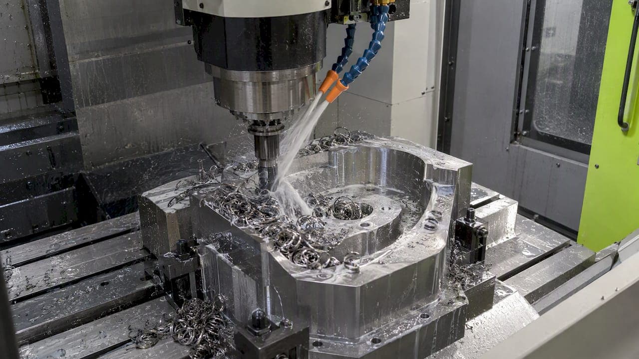
Titanium machines well when you keep heat out of the cutting edge, keep the setup rigid, and never let the tool rub. Use sharp carbide, light radial engagement, steady feed, plenty of coolant and a tool that never dwells in the cut. Most failures come from heat and work hardening, and almost all of them trace back to a tool that was allowed to rub instead of cut.
This guide is written from the shop floor view of a small CNC shop. It covers why the metal behaves the way it does, what the published numbers say about speeds and chip loads, how to handle workholding and coolant, and how to finish and inspect a part so it survives in service.
TL;DR
- Titanium is hard to machine because heat stays at the tool, the part flexes, the surface work hardens and the metal reacts chemically with the tool.
- Start from published speeds: ISCAR lists 25 to 60 m/min for heavy roughing and up to 120 m/min for light finishing, then tune from there.
- Keep radial engagement low, climb mill, never dwell, and flood the cut with coolant.
- Rigid holding and short tool stick-out matter more than any single tool brand or coating.
- Finish with sharp, honed edges and inspect for surface damage that can shorten fatigue life.
Why titanium is hard to machine
Titanium is not hard in the way tool steel is hard. It is awkward. NIST's titanium machining study names four traits that make titanium alloys difficult compared with steel: low thermal conductivity, low modulus of elasticity, work hardening and chemical reactivity. Each one shows up at the machine in a different way.

Heat stays at the edge. Because titanium conducts heat poorly, the heat of cutting does not leave with the chip or soak into the workpiece the way it does in aluminum or steel. It concentrates on the tool, so edges soften, chip and crater sooner.
The part springs away. A low modulus means the material deflects more under cutting force. A thin wall or a long slender feature pushes off the tool, then springs back, and that rubbing is exactly what builds heat and chatter. If you cut thin sections often, our notes on thin wall machining and feed rate shifts apply directly.
The surface hardens. If the tool rubs rather than shears, the skin of the part work hardens, and the next pass meets harder material than the first. That is the spiral that ends in broken end mills.
The chip wants to weld. Chemical reactivity can cause seizure between the tool and the chip. Chips stick to the flute, get re-cut, and take the edge with them.
NIST also notes that strain rates in machining span roughly 10³ to 10⁶ per second, which is part of why behavior at the cutting edge is so hard to predict from a datasheet alone. In practice, that means treat any published number as a starting point, not a promise.
Choosing tools and tool materials
Selecting cutting tool materials for titanium and nickel-based alloys is, in the words of a 2014 materials study, always a challenge for manufacturers. There is no single winner, so the useful approach is to match geometry and substrate to the grade and the operation.
Geometry
The ISCAR titanium guide recommends sharp cutting edges and, for the easier-to-machine grades, positive-rake geometry. Positive rake and increased relief angles reduce cutting forces, which means less heat and less deflection. Harder grades can call for a negative T-land to reinforce the edge, so a sharper tool is not always a stronger one. If you are unsure, begin with the sharp option on a rigid setup and move to a reinforced edge only if you see chipping.
Substrate and coating
Coated carbide is the common choice. One shop write-up emphasizes that a tool that looks right on paper still fails if the setup lets it rub. The coating is there to cut friction and protect the edge from heat, not to forgive a bad strategy.
If you are weighing substrates against a specific alloy and a heat budget, a material selection software for engineers workflow can help you compare thermal properties before you buy tooling.
Tool condition
A worn titanium tool is a hazard, not a bargain. Flank wear raises rubbing, rubbing raises heat, and heat accelerates wear. Replace edges on a schedule, based on time in cut, rather than waiting for a visible failure. Keep a log of minutes per edge for each alloy. After a few jobs, that log tells you more than any catalog.
Speeds, feeds and chip load
The published ranges are conservative compared with aluminum, and that is the point. The ISCAR guide gives these surface speeds:
| Operation | Surface speed (m/min) | Approx. SFM |
|---|---|---|
| Heavy roughing | 25 to 60 | 82 to 197 |
| Medium roughing and semifinishing | 40 to 80 | 131 to 262 |
| Finish milling and light-duty cutting | 70 to 120 | 230 to 394 |
The SFM column is our own conversion from the metric figures. Use it for orientation, then trust your machine, your holder and the sound of the cut.
For feed, CNC Cookbook puts typical chip loads at 0.127 mm per tooth (about 0.005 in), with a maximum of 0.203 mm (about 0.008 in) for both types of cutters it discusses. An older reference reports a maximum surface speed of 36.6 m/min for solid carbide cutters, roughly 120 SFM. Notice that this sits inside the low end of the ISCAR roughing window, which is a good reminder that tool type and grade shift the ceiling.
Two habits matter more than the exact number:
- Do not slow the feed to be safe. Too little chip thickness means the edge rubs. A light, steady, real chip is safer than a timid one.
- Change speed before feed when the tool is overheating. Dropping surface speed cuts heat without starving the edge of chip load.
The sweet spot is narrow. If a tool screams, smokes or turns the chip blue, stop, back off speed and check engagement before you touch anything else.
Controlling heat, chips and work hardening
Heat is the thing you are managing in every decision. ISCAR points to several levers.
Reduce radial engagement
Heat falls when you decrease width of cut. A narrow slice means each tooth spends less time in the material and more time cooling in the air before it enters again. This is why a deep, narrow pass often outperforms a wide, shallow one in titanium.
Use trochoidal paths
Trochoidal milling limits heat impact by keeping engagement uniform and chip thickness stable. It also avoids the sudden full-width burial that happens in corners and slot entries. If you do a lot of grooves, our guide to slot machining shows how toolpath choice changes the load on the cutter.
Cut below the hardened layer
ISCAR notes that high depths of cut are often used to get beneath a previously hardened layer. If an earlier pass or a skim left a work-hardened skin, a timid second pass rides on top of it and gets worse. A confident axial depth gets under it.
Climb mill
Climb milling is preferred because it makes a thick-to-thin chip, letting the thick start of the chip carry more heat out of the cutting zone, as CNC Cookbook explains. Conventional milling starts thin, rubs, and finishes thick, which is the opposite of what you want.
Never dwell
Stopping a moving tool in contact with titanium is how you create a hardened spot. Program lead-ins that arc into the cut, avoid sharp reversals and keep the tool moving through corners.
Workholding, stick-out and coolant
Rigidity first
ISCAR calls for rigid machine, workpiece and tool holding, with appropriate tool overhang. Short stick-out, a precision holder and a part clamped close to the cut remove the low-frequency flex that titanium amplifies. The same shop write-up says the sweet spot is tiny and that setups should be as rigid as possible to reduce vibration and chatter.
On a lathe the same rule gets stricter. Ifanger suggests keeping overhang from the guide bush under 3 mm for internal turning to hold rigidity and avoid chatter. That figure applies to the sliding-head setup it describes, so treat it as a benchmark for how short "short" can be.
When chatter does show up, start with the cheap fixes before you change cutters. Our post on stopping milling chatter without sensors covers four of them.
Coolant
High-pressure coolant can improve milling efficiency, according to ISCAR. The reason is simple: pressure and direction clear chips out of the cut and pull heat off the edge before it soaks in. A weak dribble does neither. Aim the nozzle at the cutting zone, not the part in general.
If you need help matching fluid to material, read our coolant selection guide. Because titanium chips can re-weld to the tool, evacuation is as important as cooling. Before you swap an end mill, run through the three chip evacuation checks we use in the shop.

Sawing and stock prep
Cutting bar or plate to size is a machining operation too, and the same rules apply: keep the blade cutting, not rubbing. For small samples and test coupons, a fine-pitch tool such as a 24TPI metal hacksaw handle with a metal-cutting blade is one option, while production stock belongs on a proper saw with coolant.
Turning, drilling and tapping
The principles carry across operations even though the details change.
- Turning: keep the insert sharp, feed steadily and avoid stopping the tool at the end of a pass. Use rigid tool holding and the shortest overhang the part allows.
- Drilling: a drill that stops cutting and starts rubbing will work harden the bottom of the hole. Use a rigid setup, steady feed and enough coolant to flush chips, and peck only as much as chip evacuation requires.
- Tapping: threads in titanium punish a dull or poorly lubricated tap. Our post on tapping aluminum explains drill size and lubricant logic, which carries over in principle, but always take speeds and tap style from a titanium-specific source.
If you are used to stainless, the habits transfer partly: both reward sharp tools and punish dwell. Our stainless steel machining guide is a good bridge, though titanium will be less forgiving about heat.
Finishing and inspecting titanium parts
Finishing is where the surface either keeps its strength or loses it. Use tools with sharp, honed edges and minimal radial engagement, which maintains surface integrity and limits residual stress and work hardening. A dull finishing tool does not just leave a worse surface finish, it can leave a damaged subsurface.
A review of conventional and non-conventional machining techniques lists surface integrity defects to look for in inspection: carbide cracking, white layer formation and microstructural alterations. These can act as stress raisers and lead to fatigue failure. For a part that sees cyclic loads, such as a bracket, a fastener or a structural mount, that is the failure mode that matters most.
A practical finishing routine:
- Leave a consistent, modest finish allowance so the final pass cuts real material.
- Put a fresh or nearly fresh edge on the finish pass.
- Keep coolant on the cut through the whole pass.
- Measure after the part has returned to room temperature, especially on tight features. Our guide to tight tolerance machining covers how heat and deflection move numbers.
- For fatigue-critical parts, ask whether the design calls for surface integrity checks beyond dimensional inspection.
Our perspective
We design and machine parts in one shop, and we talk to the person at the machine every time. That matters most on difficult materials. Titanium punishes guesswork, so the useful thing is a short loop between the drawing, the toolpath and the finished part.
Our approach to any hard-to-cut material is the same one we use on our own motorcycle parts: pick the strategy for the load the part will see, keep the setup rigid, and prove the process on a first piece before running more. Our E2 Kickstand for electric mini bikes comes from that way of working, and so does the prototype and short-run work we quote for engineers and small manufacturers.
If you are choosing between a strategy that is quick to program and one that protects the tool and the surface, we would pick the second every time. A part that runs well the first time costs less than one that is remade.
Drake
Work with a machinist you can talk to
If you have a bracket, fixture or prototype that needs real machining, we handle design questions, revisions and shipping from one shop in Athens, Alabama, with direct access to the machinist. Send us your drawing, material and quantity, and we will tell you how we would approach it. See our prototype, short-run and fixture machining services.

If you ride, our E2 Kickstand for the KTM SX-E 2, GASGAS MC-E 2 and Husqvarna EE 2 is a CNC-machined, bolt-on replacement for the factory triangle stand, listed at $100-$105. For a wider look at how we think about parts like it, read our guide to machining motorcycle parts.
FAQ
Is titanium really that hard to machine?
It is harder than steel or aluminum for specific reasons, not because it is simply hard. NIST points to low thermal conductivity, low modulus, work hardening and chemical reactivity. With sharp tools, light engagement, rigid holding and good coolant, it cuts predictably.
What is the most common mistake when cutting titanium?
Letting the tool rub instead of cut. That happens with dull edges, feeds that are too light, dwell at the end of a move or a flexible setup. Rubbing builds heat and hardens the surface, and the next pass gets worse.
What tools should I use?
Start with sharp, coated carbide with positive-rake geometry and generous relief for easier grades. Move to a reinforced edge only if you see chipping on harder grades, as the ISCAR guide describes. Match the substrate to the alloy and operation.
Do I need high-pressure coolant?
It is not mandatory for every job, but it can improve milling efficiency by clearing chips and removing heat from the cut. At minimum, use a steady, well-aimed flow rather than a trickle.
Sources
- Machining Process Measurements: A Titanium Machining Example (NIST)
- Machining Titanium (ISCAR reference guide)
- Titanium Machining How To: Tooling, Tips, and Techniques
- Chapter 9: Milling Difficult Features (GlobalSpec)
- Influence of Tool Materials on Machinability of Titanium Alloys
- Indications for the machining of Titanium alloys (Ifanger)
- An overview of conventional and non-conventional techniques (Manufacturing Review, 2020)