
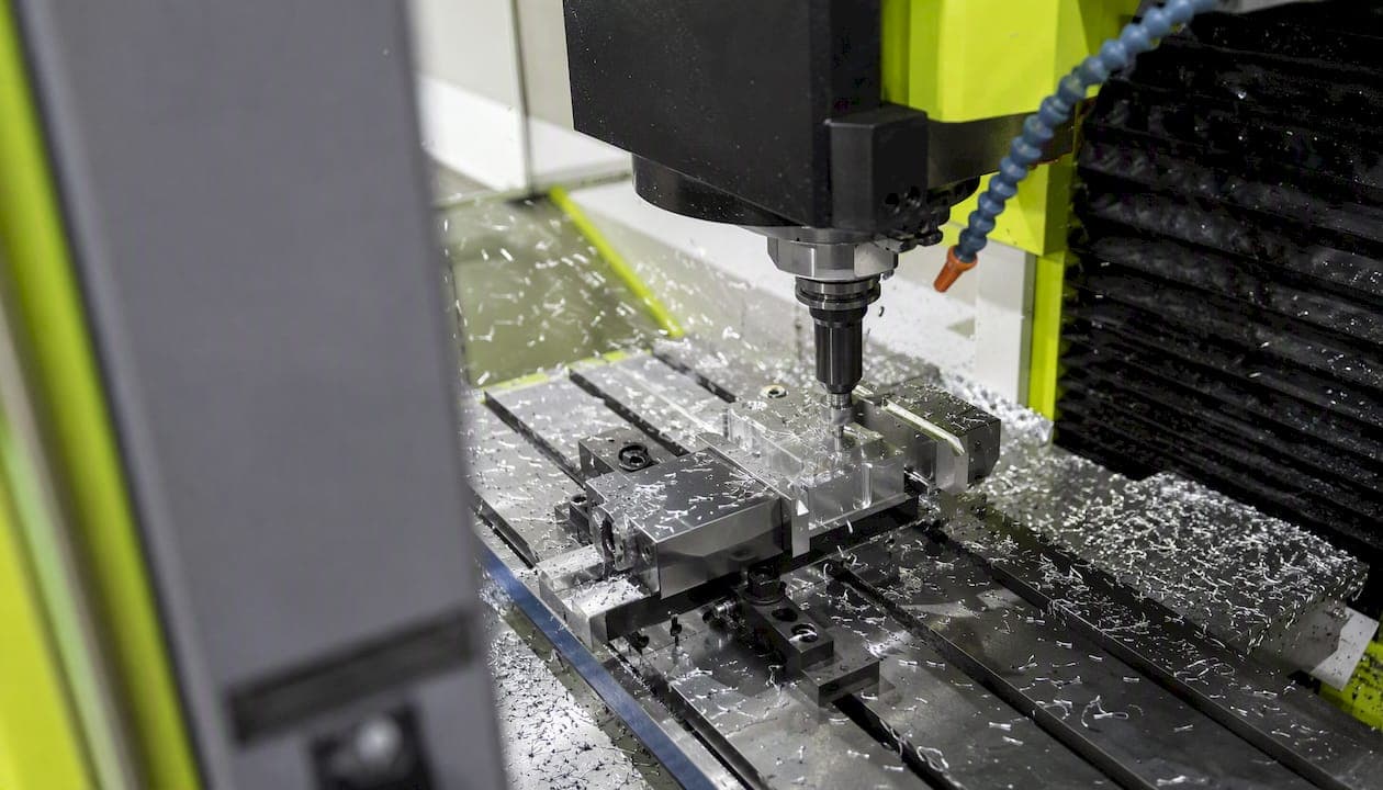
Machine stainless steel predictably by pairing sharp ISO M-style geometry with a PVD-coated carbide tool, committing to a depth of cut that gets below the work-hardened skin, and pushing heat and chips out with targeted high-pressure coolant. That is the whole game. Everything else is tuning.
For 304/316 austenitic grades, start rough turning at moderate surface speeds with a feed sufficient to cut below the hardened surface layer. Finish turning should also use a depth of cut that penetrates the hardened layer to avoid rubbing. For carbide milling, use a surface speed appropriate for 304, and reduce speeds slightly for 316. These are starting values from published industry guidance, not gospel. Dial them in based on your machine's rigidity and your toolmaker's specific recommendations.
- Use ISO M-designated inserts or endmills rated for stainless and heat-resistant alloys.
- PVD-coated fine-grain carbide is the default substrate for 300-series austenitic grades.
- Feed above the minimum chip thickness. Rubbing is what causes work hardening, not cutting.
- Coolant aimed at the shear zone, not sprayed generally at the part.
- Never take a skim finish pass on 304 or 316. If your finish DOC is under 0.010 in, you are rubbing on the hardened skin, not cutting through it.
Pro Tip: On austenitic grades, the instinct to "sneak up" on a dimension with a light final pass is exactly wrong. A 0.003 in finish pass on 304 does not cut; it rubs, work-hardens the surface, and leaves a torn finish. Commit to at least 0.010 in on that last pass.
Key Takeaways
Stainless steel machining requires sharp PVD-coated geometry, a depth of cut that penetrates the work-hardened skin, and targeted coolant to control heat and chip evacuation from the first pass to the last.
| Point | Details |
|---|---|
| Commit to depth of cut | Finish depth of cut on 304/316 stainless should be sufficient to penetrate the hardened surface layer to avoid rubbing and work hardening. |
| Feed above minimum chip thickness | Increasing feed, not reducing speed, is the correct fix for built-up edge and rubbing in austenitic grades. |
| PVD coating over CVD | PVD coatings (2–5 µm) preserve a sharper edge than CVD (8–20 µm), which matters on work-hardening grades. |
| Control heat with targeted coolant | HPC at 50–120 bar through the tool is the most effective method for deep holes and HEM milling in stainless. |
| Flying Chip Factory | Prototype and short-run stainless machining with direct machinist access; send STEP files with tolerances and grade for a fast quote. |
How stainless steel machining differs by alloy family
Stainless is not one material. The family you are cutting determines almost everything about your tooling and parameter choices, and treating all stainless the same is the fastest way to burn through inserts.
Machinability ranking, best to worst (approximate):
- 303 (free-machining austenitic): sulfur additions break chips; closest to carbon steel in behavior.
- 410/416/420 (martensitic/ferritic): harder but more thermally conductive than austenitic; machines more predictably.
- 430 (ferritic): moderate machinability, less prone to work hardening than 304.
- 304/304L (austenitic): high work-hardening rate, low thermal conductivity, gummy chips, BUE risk.
- 316/316L (austenitic): similar to 304 but slightly tougher; run 10–15% slower.
- 17-4 PH (precipitation-hardened): machinability depends heavily on condition; H900 condition is significantly harder than annealed.
- Duplex/super-duplex (2205, 2507): highest strength and work-hardening of the group; most demanding on tooling.
The three properties that drive all the difficulty in austenitic stainless machining are worth understanding at a mechanical level, not just as a warning label.
Work hardening is the biggest one. Austenitic grades like 304 and 316 harden rapidly at the surface when the tool rubs rather than cuts. That hardened layer is typically 0.002–0.010 in deep. Any subsequent pass that does not penetrate it will rub on hardened material, accelerating tool wear and making the problem worse with each pass.
Low thermal conductivity means heat generated at the cutting edge has nowhere to go except into the tool. Carbon steel dissipates heat into the chip and the workpiece. Stainless keeps it concentrated at the tool tip, which accelerates diffusion wear and shortens insert life dramatically without aggressive coolant.
Ductility and toughness produce long, stringy chips and a tendency toward built-up edge (BUE), where workpiece material welds to the cutting edge. BUE changes the effective geometry of the tool and tears the surface rather than cutting it cleanly.
| Family | Typical Grades | Machinability Notes | Common Problems |
|---|---|---|---|
| Free-machining austenitic | 303 | Best in class for austenitic; chips break cleanly | Sulfur reduces corrosion resistance; not weldable |
| Standard austenitic | 304, 304L, 316, 316L | High work-hardening, low thermal conductivity | BUE, stringy chips, short tool life |
| Martensitic | 410, 416, 420 | More thermally conductive; harder at higher carbon | Abrasive wear; check hardness before cutting |
| Ferritic | 430 | Moderate machinability; less work hardening | Galling on threads; use sharp tools |
| Precipitation-hardened | 17-4 PH | Condition-dependent; annealed cuts well, H900 does not | Abrasive wear in aged condition |
| Duplex | 2205, 2507 | Highest strength; most demanding | Rapid work hardening, chatter, short tool life |
Material condition matters as much as grade. Annealed 304 bar stock cuts noticeably better than cold-drawn 304. Cold-drawn material has a pre-existing hardened skin from the drawing process, so your effective starting DOC needs to account for that. Check the material cert for hardness (Brinell) before setting your first pass parameters. Just as temper and condition affect aluminum machinability, the same principle applies to stainless: the metallurgical state of the stock changes your starting point.
Selecting the right tools for stainless steel
Substrate and coating
Fine-grain carbide with a PVD coating is the standard starting point for 300-series austenitic grades. The Nickel Institute's machining guide specifically recommends PVD coatings for austenitic stainless because they preserve a sharper cutting edge than CVD. PVD coatings run 2–5 µm thick; CVD coatings are 8–20 µm. That thickness difference rounds the cutting edge enough to increase rubbing on the work-hardened skin, which is the last thing you want on 304 or 316.
TiAlN and AlCrN are the most common PVD choices. AlCrN holds up better at higher temperatures, which matters in stainless where heat concentrates at the tip. For martensitic grades like 410 or 416, cobalt HSS is a viable option at lower speeds, particularly for drilling and tapping where carbide's brittleness becomes a liability.
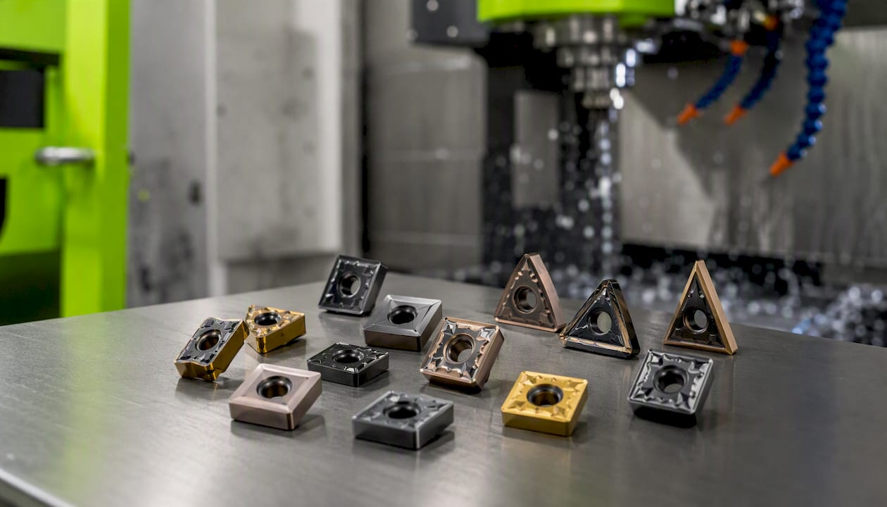
Pro Tip: Never use CVD-coated inserts as your first choice on austenitic stainless. The thicker coating rounds the edge, increases cutting forces, and promotes the rubbing that triggers work hardening. PVD first, every time.
Geometry and edge prep
Positive rake is non-negotiable. A positive rake angle reduces cutting forces and the tendency to push material rather than shear it. For inserts, a light hone of 0.001–0.002 in is appropriate; a heavy T-land or large chamfer increases the force required to initiate the cut and promotes BUE. Chipbreaker selection matters: use a medium-duty chipbreaker for roughing (to handle the chip load) and a sharper, lighter chipbreaker for finishing.
Endmill selection
Helical Solutions recommends 4-flute endmills for general stainless milling and slotting, where chip clearance is a priority. Five-flute tools work well for finishing passes and high-efficiency milling (HEM) where radial engagement is low and chip load per tooth is the limiting factor. Helix angle guidance: 30–40° for roughing, 40°+ for finishing. Variable-pitch endmills are worth the premium on stainless because the irregular tooth spacing disrupts the harmonic that causes chatter, particularly in longer reaches or thin-wall features.
Drills and taps
For drilling, a 135° split-point or parabolic-flute geometry is the right call. Standard 118° points require more thrust to penetrate stainless and are more prone to walking. For holes deeper than 5×D, through-coolant drills are not optional; they are the difference between a clean hole and a broken drill. Tapping stainless is where a lot of shops lose parts. Spiral-flute taps work best for blind holes (they pull chips up and out); spiral-point (gun) taps are better for through holes. Use sulfurized tapping oil on non-free-machining grades. Low RPM, high torque, and a quality tap holder with tension/compression float.
Speeds, feeds, and depths of cut: practical starting points
The conversion formula
RPM = (SFM × 3.82) / tool diameter (inches)
For a 0.5 in endmill at 300 SFM: RPM = (300 × 3.82) / 0.5 = 2,292 RPM. That is your starting spindle speed. Chip load then sets your feed rate: Feed (IPM) = RPM × chip load × number of flutes.
Starter parameters by grade and operation
These values come from published SFM and feed guidance for 304 and 316, adjusted for 303 and 17-4 PH based on machinability differences. Treat them as a starting point, not a final setting.
How to tune parameters on the machine
- Start at the lower end of the SFM range and the middle of the chip-load range.
- Watch the chip color and shape. Silver or light gold chips are fine. Blue or purple means too much heat; reduce SFM or increase coolant pressure.
- If you see BUE (shiny, torn surface), increase feed first, not speed. Maintaining chip thickness above the minimum is what prevents rubbing.
- If the tool chatters, reduce radial engagement before reducing SFM. Chatter is usually a rigidity or engagement problem, not a speed problem.
- Increase DOC if you suspect you are cutting on a hardened layer. A deeper pass that gets under the skin cuts cleaner than a shallow pass that rubs on it.
Depth of cut for roughing should be aggressive enough to get below the work-hardened skin. High-efficiency milling and HPC coolant are the two biggest levers for improving tool life in stainless without changing the tool itself.
Operation-specific tactics for milling, turning, drilling, and tapping
Milling
- Climb milling only. Conventional milling on stainless increases rubbing on entry and promotes BUE. Seco Tools and every major toolmaker agree on this. Climb milling starts the chip at maximum thickness and exits thin, which is the opposite of what causes work hardening.
- Use HEM/trochoidal paths for pockets and slots. Constant-engagement toolpaths keep chip load consistent and prevent the heat spikes that come from full-width entry. For slotting, drop to 3–4 flutes to maintain chip clearance. A 5-flute tool in a full-width slot on 316 will pack chips and break.
- Ramp or helical entry into pockets. Never plunge straight down into stainless with a flat endmill. Ramp at 1–3° or use a helical entry at a conservative pitch. Plunging concentrates heat and axial force at the center of the tool where chip clearance is worst.
- Slotting guidance: match flute count to the slot width. For a slot equal to tool diameter, use a 4-flute maximum and reduce feed by 20–30% versus side milling. Chip evacuation is the constraint, not cutting force.
Pro Tip: For thin-wall features in 304 or 316, take multiple light finishing passes rather than one heavy one, but make sure each pass still exceeds 0.010 in DOC. The goal is to stay below the hardened skin while keeping cutting forces low enough not to deflect the wall.
Turning
Maintain a minimum feed rate throughout the pass. Dwell in turning (the tool pauses or slows at a shoulder) work-hardens the surface at that point and creates a hard spot the next pass has to cut through. Use positive-rake inserts, keep overhang under 3×D for boring bars, and support the workpiece with a tailstock or steady rest whenever the length-to-diameter ratio exceeds 4:1.
Drilling
Peck drilling is mandatory on austenitic grades. Machining Doctor recommends peck depths of 1×D or less per peck, no dwell at the bottom of the peck, and a minimum feed per revolution of 0.003–0.004 ipr to prevent rubbing at the drill tip. For holes deeper than 5×D, through-coolant is the only reliable way to evacuate chips and keep the drill tip cool. A parabolic-flute drill handles chip evacuation better than a standard jobber drill in deep-hole stainless work.
Tapping
Low RPM, high-quality tapping oil, and the right tap geometry. Spiral-flute taps for blind holes, spiral-point for through holes. For M6 or 1/4-20 taps in 304, run at 50–80 RPM with a sulfurized or chlorinated tapping oil. A tension/compression tap holder prevents the tap from loading up when the machine reversal is slightly off. For thread quality verification on critical parts, go/no-go gauges are the fastest way to confirm conformance without measuring every thread.
Coolant and lubrication: which method to use and when
Heat is the primary failure mechanism in stainless machining. Low thermal conductivity means the workpiece does not absorb heat the way carbon steel does, so the tool tip carries almost all of it. Coolant is not optional; it is a process variable.
It cools effectively and provides moderate lubrication. The limitation is pressure: standard flood at 20–40 PSI does not reliably break the vapor layer at the cutting edge in deep holes or high-speed milling.
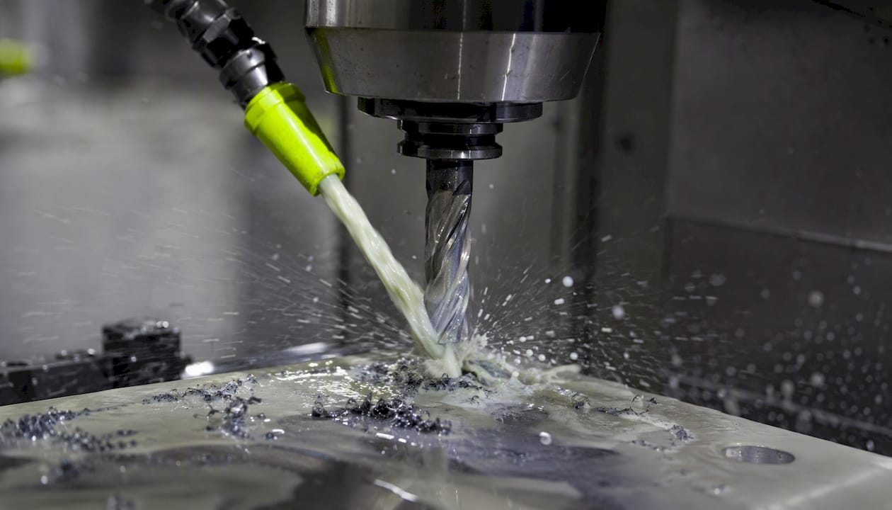
High-pressure coolant (HPC) through the tool is the step change. HPC at 50–120 bar breaks the vapor barrier, forces chips out of the flutes, and drops tool tip temperature significantly. For drilling deeper than 3×D and any milling operation where chip packing is a risk, HPC through the spindle is worth the machine investment.
Sulfurized or EP (extreme pressure) oils are the right choice for tapping and threading non-free-machining grades. They provide the boundary lubrication that water-based emulsions cannot at the low speeds and high contact pressures of tapping.
Minimum quantity lubrication (MQL) works on some stainless operations, particularly finishing passes where chip volume is low and heat generation is moderate. It is not a substitute for flood or HPC in roughing or deep drilling.
| Method | Best For | Pressure/Concentration | Limitation |
|---|---|---|---|
| Flood emulsion | General milling, turning | 5–10% concentration, 20–40 PSI | Insufficient for deep holes; vapor layer at high speed |
| HPC through-tool | Deep drilling, HEM milling | 50–120 bar | Requires machine spindle capability |
| Sulfurized/EP oil | Tapping, threading | Neat or diluted | Not suitable for flood on most machines |
| MQL | Light finishing, shallow milling | Micro-droplet | Not adequate for roughing or deep holes |
Pro Tip: Aim coolant at the shear zone, not at the top of the tool or the part surface. Mis-aimed flood creates turbulence and can actually aerate the cutting zone, reducing cooling effectiveness. On a milling operation, the nozzle should point at the leading edge of the cut, not the center of the cutter.
Keeping chips moving and the part rigid
Chip control and workholding are where stainless jobs either run smoothly or fall apart. Stringy austenitic chips will wrap around a tool, jam a spindle, and ruin a part in seconds if the setup does not account for them.
- Minimize tool overhang. Every extra inch of stick-out reduces rigidity exponentially. Keep endmill overhang under 3×D whenever possible. For longer reaches, use a stub-length tool in a longer holder rather than a long-reach endmill.
- Clamp close to the cut. Soft jaws, step clamps, and vise stops should be as close to the cutting zone as the operation allows. Knife-edge soft jaws work well for thin-wall parts because they distribute clamping force along a line rather than a point, reducing distortion.
- Route coolant to lead chips away from flutes. On a milling operation, chips should exit away from the next tooth's entry. If chips are re-entering the cut, they are getting re-cut, generating heat, and scoring the surface.
- Use chipbreaker inserts in turning. A medium-duty chipbreaker on a roughing insert breaks the long stringy chips that austenitic grades produce. Without it, you are stopping the machine every few minutes to clear a bird's nest.
- Peck cycles for drilling: 1×D per peck for standard drills in 304/316, retract fully to clear chips, no dwell at the bottom. For 5×D holes with through-coolant, you can extend peck depth to 1.5×D, but watch chip color on retract. Drilling austenitic stainless is especially sensitive to dwell; even a half-second pause at the bottom of a peck work-hardens the surface and the next peck starts on hardened material.
- Hydraulic chucks or collet chucks over standard ER collets for any operation where runout matters. Runout in stainless milling translates directly to uneven chip load per tooth, which means some teeth are rubbing while others are cutting, accelerating wear unevenly.
Pro Tip: For thin-wall stainless parts, fill the bore with low-melt alloy (Cerrobend) or use a mandrel before finish machining the OD. The added support prevents the wall from deflecting under clamping and cutting forces, which is the most common cause of out-of-round thin-wall parts.
Diagnosing and fixing the most common stainless machining problems
1. Built-up edge (BUE)
Symptom: Shiny, torn surface finish; material smeared rather than cut; insert edge looks dull but is actually coated with workpiece material.
Root cause: Feed too low, allowing the tool to rub rather than cut; or insert geometry too blunt for the grade.
Fix: Increase feed rate first. If BUE persists, switch to a sharper PVD insert with a lighter hone. Check coolant aim. Harvey Performance's stainless guide identifies BUE as one of the four dominant failure modes and recommends adjusting feed and coolant before changing the insert grade.
2. Chatter and vibration
Symptom: Orange-peel surface finish, variable Ra across the part, audible harmonic during the cut.
Root cause: Insufficient rigidity in the setup, excessive tool overhang, or resonance at the chosen spindle speed.
Fix: Reduce radial engagement before reducing SFM. Shorten tool overhang. Try a variable-helix endmill, which disrupts the harmonic that drives chatter. BSSA guidance emphasizes machine and tooling rigidity as the primary defense against chatter in stainless.
3. Work hardening during drilling
Symptom: Drill breaks on re-entry after a peck; increasing thrust force through the hole; drill tip shows rapid wear.
Root cause: Dwell at the bottom of the peck, or feed rate too low, allowing the drill tip to rub rather than cut.
Fix: Eliminate dwell completely. Increase feed per revolution to at least 0.003–0.004 ipr. Use through-coolant if the hole is deeper than 3×D.
4. Premature insert wear or sudden tool failure
Symptom: Insert life significantly shorter than expected; surface finish degrades rapidly after a few parts.
Root cause: Cutting on a hardened layer (DOC too shallow), incorrect grade for the material, or heat buildup from insufficient coolant.
Fix: Increase DOC to get below the hardened skin. Verify the insert ISO M designation matches the grade. Increase coolant pressure or switch to HPC. Monitor spindle load: a rising load trend without a change in parameters usually means the insert is dulling faster than expected.
Pro Tip: Track spindle load on your machine's control display during a stainless run. Stop and inspect before the part is scrap.
Shop-tested tweaks from Flying Chip Factory
Before the first chip flies on a new stainless job, the setup sequence matters as much as the parameters. At Flying Chip Factory, the order is: workholding first, then tool selection and stick-out, then DOC and feed, then coolant aim. Getting the sequence wrong means you are tuning parameters on a setup that was never going to work.
- Spindle run-in check: On a new tool, run the spindle at the target RPM for 30 seconds before engaging the cut. This seats the tool in the holder and reveals any runout before it shows up as a bad part.
- Pre-cut checklist: Verify tool overhang is under 3×D. Confirm coolant nozzles are aimed at the shear zone. Check that the workpiece is clamped within 1 in of the first cut. Confirm the insert or endmill is the correct ISO M designation for the grade.
- Preferred tooling combinations: For pockets in 304 or 316, a 5-flute variable-helix endmill in an HEM toolpath at 10–15% radial engagement outperforms a 4-flute at full-width engagement in almost every case. For slotting, drop to 4 flutes and reduce feed by 25%.
- First-run parameter logging: Write down the actual SFM, chip load, DOC, and coolant pressure used on the first successful part. That log is worth more than any starting-value table on the second run of the same job.
- When to recommend an alternative: If a customer's design calls for 316L but the tolerances are achievable in 303 and corrosion resistance is not the primary driver, Flying Chip Factory will flag that. Free-machining grades cut faster, hold tighter tolerances more consistently, and cost less in tool wear.
Pro Tip: When quoting a stainless job, send the material cert with your drawing. The difference between annealed and cold-drawn 304 changes the starting parameters enough that a quote without it is a guess. Flying Chip Factory prefers STEP or IGES files with a PDF drawing showing critical tolerances and surface finish callouts.
For slotting operations specifically, the chip clearance rules above apply directly: fewer flutes, lower feed, and HEM paths wherever the geometry allows.
Quick reference: conversions and starter parameters
SFM to RPM conversion: RPM = (SFM × 3.82) / D (inches)
Worked example: 0.25 in drill in 304 at 200 SFM RPM = (200 × 3.82) / 0.25 = 3,056 RPM Feed = 3,056 × 0.003 ipr = 9.2 IPM
Starter table for common tool diameters in 304/316 (carbide, flood coolant):
- Verify these values against your toolmaker's published data for the specific tool geometry.
- Adjust SFM down 10–15% for 316 versus 304 as a starting point.
- Log actual tool life and surface finish on the first run.
- Adjust chip load up before reducing SFM if you see BUE or rubbing.
Pro Tip: Keep a simple log sheet at the machine: tool, grade, SFM, chip load, DOC, coolant type, and parts-per-edge. After three or four jobs on the same material, you will have your own calibrated starting points that beat any published table.
Finishing, deburring, and post-process notes
Finishing passes on stainless require the same discipline as roughing: stay below the hardened skin. A finish DOC under 0.010 in on 304 or 316 is rubbing, not cutting, and it will leave a torn, work-hardened surface that is harder to deburr and more prone to corrosion at the edge.
- Insert selection for finishing: Use a sharper insert with a lighter hone (0.001 in or less) and a wiper geometry if your insert holder allows it. Wiper inserts produce a better Ra at higher feed rates, which means you can maintain minimum chip thickness while still hitting a fine finish.
- Deburring: Light CAM deburring passes (a chamfer tool or deburr cycle in the CAM software) are the cleanest option. Ceramic media tumbling works well for batch deburring of small parts. Hand deburring with a carbide scraper is fine for prototypes. Avoid aggressive grinding or abrasive wheels on visible surfaces; they generate heat and can leave embedded abrasive particles that compromise corrosion resistance.
- Heat tint: If a finishing operation or welding leaves a blue or gold heat tint on the surface, that discoloration indicates chromium depletion in the surface layer, which reduces corrosion resistance. For critical parts, pickling paste or electropolishing restores the passive layer. For cosmetic parts, mechanical removal with a fine abrasive followed by passivation per ASTM A967 is the standard approach.
- Safety with hot chips: Stainless chips are sharp, long, and retain heat longer than carbon steel chips. Leather gloves, chip hooks, and a chip conveyor or frequent chip clearing are not optional. Never clear chips by hand or with compressed air aimed at the operator.
- Coolant disposal: Spent water-soluble coolant from stainless machining contains tramp oil and metal fines. Dispose of it per your local regulations; most municipalities require treatment before drain discharge. Check with your coolant supplier for recycling or disposal options.
An honest perspective on machining stainless
The conventional advice on stainless machining is not wrong, but it is incomplete in one important way: it focuses almost entirely on what to avoid (skim passes, dwell, low feed) without explaining why those things cause the specific failures they do. A machinist who understands that austenitic stainless work-hardens because the tool is rubbing, not because the material is inherently difficult, will make better decisions at the machine than one who is just following a rule list.
The other thing most guides understate is the cost of conservative parameters. Running 304 at 150 SFM to "play it safe" does not extend tool life; it reduces chip thickness below the minimum, promotes rubbing, and accelerates BUE. The tool dies faster at 150 SFM than at 275 SFM with the right chip load. Stainless rewards commitment. The shops that struggle with it are usually the ones making small, cautious adjustments when the material needs a decisive change in engagement.
At Flying Chip Factory, the priority on stainless jobs is repeatability from the first part to the last. That means logging the parameters that worked, not just the ones that were tried. It also means telling a customer when their material choice is making the job harder than it needs to be. If 303 achieves the design intent, there is no reason to fight 316.
Flying Chip Factory handles your stainless steel parts
Stainless machining rewards shops that have done it before. Flying Chip Factory runs prototype and short-run CNC machining in stainless steel grades including 303, 304, 316, and 17-4 PH, with direct access to a machinist from the first quote to the final part. No account manager relay. No revision cycle that takes a week.

For a fast quote, send a STEP or IGES file with a PDF drawing that calls out critical tolerances, surface finish (Ra), material grade, and any post-process requirements (passivation, heat treat condition). If you are not sure which grade fits your application, that is a conversation worth having before the job is quoted. Flying Chip Factory can advise on material selection, tolerance stack-up, and fixturing before a single chip flies.
Request a quote or ask a machinability question at Flyingchipfactory.
Sources
These sources are worth bookmarking for verifying insert grades, chipbreaker codes, and SFM tables before you set up a new stainless job.
- Machining the Austenitic Chromium‑Nickel Stainless Steels (Nickel Institute PDF)
- Machining Stainless Steel | Seco Tools
- Slaying Stainless Steel: Machining Guide - In The Loupe (Harvey Performance)
- Machining Austenitic Stainless Steel (304 and 316): Work Hardening and Tool Selection | Industry Resource Center
- Machining Stainless Steel - Machining Doctor