
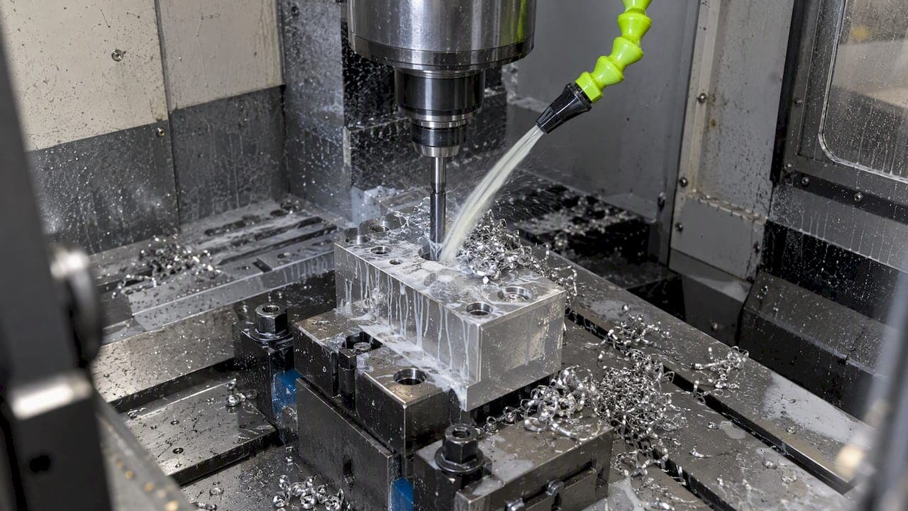
Check coolant and nozzle alignment first, then confirm chipbreaker geometry and feeds are matched to the material, since misaligned flow and the wrong tool geometry cause most chip evacuation problems. Enable through-coolant or add an auger or conveyor when you're running continuous production or stringy materials. Always stop the spindle and use a hand tool or brush to clear packed chips, and follow lockout/tagout before servicing the evacuation system.
TL;DR:
- Use through coolant once a hole exceeds roughly three times its diameter, or whenever long chipping material makes external flushing unreliable.
- Sandvik recommends roughly 80 bar for most chip control work and 150 bar for resistant materials; test pressure separately from feed rate.
- Air jets suit light, dry chips; conveyors or augers handle wet, hot, abrasive chips, but require space, coolant drainage, and jam protection.
- If coolant and tooling changes fail, inspect holder seating, spindle runout, and tool stick out, since vibration can mimic poor chip evacuation.
- Change one setting per test cut and record sound, current, and chip shape; after two or three failed adjustments, inspect mechanical rigidity.
Symptoms and quick checks that show chip evacuation is failing
Before you start swapping tools or adjusting feeds, confirm you actually have an evacuation problem and not something else wearing the same mask. The clearest signs show up in sound and current draw first, then in the chips themselves.
A consistent cutting sound usually means chips are clearing cleanly. An interrupted or grinding sound, paired with a spike in feed or spindle current, often means a flute has packed or a chip has wedged against the cutting edge, a pattern noted in Sandvik Coromant's drilling guidance. Visual evidence backs this up: long stringy chips that never break, a flute packed solid with material, a rough or scored hole wall, or chip marks that show recutting on the finished surface.
Three checks take less than five minutes and rule out the obvious causes:
- Pull the tool and inspect the flutes for packed material or buildup near the tip.
- Verify coolant is actually reaching the cutting zone, not just spraying nearby, and check nozzle alignment and flow.
- Confirm the material batch hasn't changed, since a different heat treat or alloy mix can shift chip behavior without any other change on your end.
If all three check out clean, the problem is more likely geometry, speeds, or machine rigidity, which the next sections cover.
Root causes: tool geometry, material, and machine rigidity that make chips pack
Chips pack for one of three reasons: the tool isn't shaping them correctly, the material doesn't want to break cleanly, or the setup is moving enough to disrupt an otherwise good cut.
Flute profile, chipbreaker design, helix angle, and margin width all determine how a chip curls and separates from the workpiece. A chipbreaker ground for aluminum won't do much for a gummy alloy, and a helix angle tuned for fast evacuation in one material can pack solid in another.
Material matters just as much as tool design:
- Some stainless grades and nickel alloys produce long, stringy chips that resist breaking and tend to wrap around the tool or wedge in the flute.
- Softer, gummy materials often adhere to the cutting edge instead of shearing cleanly, which compounds the packing problem.
- Harder, more brittle materials typically break into short chips that clear easily but can still jam in deep or narrow passages.
Machine and setup issues often masquerade as chip evacuation failures. Runout from a worn or poorly seated holder, excessive tool stick-out, and general lack of rigidity all introduce vibration that disrupts chip formation, which leads to packing and recutting even when the tool and coolant setup are correct. A closer look at your toolholder condition and stick-out often resolves what looks like a clearing problem; our notes on diagnosing milling chatter cover the same rigidity checks that apply here.
Practical fixes: tooling, feeds/speeds, coolant, and cut strategy
Most evacuation problems respond to a short sequence of adjustments rather than a full tooling overhaul. Work through these in order and change one variable at a time so you know what actually fixed it:
- Match the chipbreaker to the material: use a more aggressive chipbreaker geometry for long-chipping alloys like certain stainless and nickel grades.
- Adjust feed before speed: increasing feed often promotes better chip breaking, while reducing speed can cut down on material adhesion to the cutting edge.
- Switch to internal or through-coolant for deep holes and difficult materials, since external coolant struggles to reach the cutting zone once a hole gets much past shallow depth.
- Tune coolant pressure to the job: Sandvik Coromant recommends roughly 80 bar (1160 psi) for chip breaking in most turning and drilling applications, rising to around 150 bar (2176 psi) for materials that resist breaking.
- Use peck drilling for deep holes, choosing peck depth based on material and diameter, and consider ejector drill designs when the length-to-diameter ratio gets high.
- Reduce tool stick-out wherever the job allows, and verify holder seating and spindle runout before blaming the tool or coolant.
For material selection on new jobs, it helps to know a given alloy's chipping tendency ahead of time. A materials overview for CNC machining breaks down common chipping behavior across metals and plastics, which is useful when you're quoting or planning a new part.
Internal coolant delivery is specifically recommended once a hole passes roughly three times its diameter, and for any long-chipping material regardless of depth, because external coolant can't reliably flush chips out of a deep, narrow passage.
Pro Tip: When troubleshooting, change only coolant pressure or only feed rate in a single test run, never both, so you can tell which adjustment actually fixed the chip form.
Setup tweaks round out the fix list. Shortening stick-out, checking holder condition, and isolating vibration sources often solve packing issues that look like a coolant or tooling problem on the surface. If you're cutting slots rather than drilling, the same feed and chipbreaker logic applies, with some added considerations for wall engagement covered in our slot machining guide.
Machine- and shop-level solutions: conveyors, augers, air jets, and ejector drilling
When tooling and coolant adjustments aren't enough, usually because you're running continuous production or working with wet, hot chips in volume, hardware becomes the practical answer.
- Add a hinged-steel-belt conveyor or auger for wet, hot chips or high-volume runs, since these are built to handle continuous abrasive discharge without clogging, according to Transcon Conveyor's overview of chip removal systems.
- Use air jets or nozzle-based systems for light, dry chips where a full conveyor would be overkill.
- Design conveyors around belt type, incline angle, discharge point, coolant drain integration, and jam protection, since each machine layout and chip type calls for a different configuration.
- Choose ejector drilling for high length-to-diameter bores, where coupled coolant flow and head geometry actively pull chips out rather than relying on gravity or flush alone.
Deep-hole and ejector drilling deserve a closer look because small design changes carry outsized effects. Modeling work on ejector deep-hole drilling chip evacuation shows that flute geometry and head design strongly influence clogging risk, particularly as the hole's length-to-diameter ratio climbs. A head geometry that clears chips well at a 5:1 ratio can clog repeatedly at 10:1 without a coolant flow adjustment.
The tradeoffs with any hardware addition are real: conveyors and augers take up floor space, carry an upfront cost, and need coolant recovery plumbed into the layout. For shops scaling into longer production runs, our guide to short-run CNC production covers when that investment starts to pay off versus sticking with manual clearing.
Safety and guarding when clearing chips or fitting evacuation hardware
Chip evacuation work puts hands near moving tooling and hot material, so guarding and procedure matter as much as the fix itself.
OSHA's machine guarding standard requires protection against flying chips and outlines safeguarding methods including barrier guards, safe-distance positioning, and automated feeding or ejection, while making clear that any guard added must not introduce a new hazard of its own.
Safe practice on the shop floor is straightforward:
- Stop the spindle completely before clearing any packed chip, and use a hand tool, hook, or brush rather than your fingers.
- Never hand-feed material or reach toward a running tool to clear an obstruction.
- Apply lockout/tagout before servicing the evacuation system whenever hazardous energy could be present, with minor servicing exemptions applying only under the narrow conditions OSHA defines.
Automatic feeding and ejection methods, including pneumatic air jets, mechanical arms, and vacuum systems, reduce the need for operators to reach into the cutting zone at all, which is the core safety argument for upgrading hardware beyond the cost and throughput benefits.
Diagnose and verify: a troubleshooting checklist and what to measure
A repeatable test beats guesswork every time, especially when you're chasing an intermittent jam that only shows up every tenth part.
- Reproduce the problem on a consistent test cut, whether that's a slot, a hole, or a short production run.
- Change exactly one variable: nozzle angle, coolant pressure, feed rate, or tool geometry.
- Observe and note the cutting sound, amperage reading, and chip form after the change.
- Record the result and compare it against your baseline before moving to the next variable.
A few simple instruments make this process measurable instead of anecdotal. A coolant pressure gauge confirms you're actually hitting your target pressure at the nozzle, an amp meter or power log catches the current spikes that signal packing before it becomes audible, and listening closely to cut sound, sometimes with something as simple as a mechanic's stethoscope, helps you catch an interrupted cut early.
Pro Tip: Keep a chip sample taped to a log sheet next to each test run. A visual record of chip shape across five or six adjustments shows the trend faster than memory alone.

Photograph flute condition and hole surface finish alongside the chip samples, and escalate to a holder or machine rigidity inspection if two or three variable changes in a row produce no improvement. At that point the issue is more likely mechanical than it is a tooling or coolant setting, a pattern that matches Harvey Performance's troubleshooting guidance on end mill issues around vibration and worn components.
Shop perspective from our CNC machining shop
Most of our own evacuation decisions come down to matching the hardware to the job rather than defaulting to one setup. Long bores get through-coolant drills from the start, since fighting a deep hole with external flush alone wastes more time than the tooling upgrade costs. Stainless batch runs earn a conveyor addition once volume justifies it. Because one machinist handles both the design and the cutting, a chip problem spotted mid-run gets a geometry or coolant change the same day instead of waiting on a review cycle. For more shop-level breakdowns like this one, our technical blog covers related fixture and setup topics.
— Drake
How we can help with prototype and short-run machining
If chip evacuation problems are slowing down a prototype or a short production run, we build the coolant plumbing and chipbreaker selection into the job from the start rather than troubleshooting after the fact. 
Our services cover prototype machining, short-run production, and fixtures, brackets, and support parts, with one machinist handling design and cutting so a chip-clearing issue gets solved the same day it's spotted.
- We select chipbreaker geometry and coolant delivery by material before the first part runs, not after a jam shows up.
- Direct contact with the machinist means a mid-run adjustment doesn't wait on a support queue.
- Our E2 Kickstand for KTM SX-E 2, GASGAS MC-E 2 & Husqvarna EE 2 shows the same chip-conscious machining approach applied to an in-house product, priced at $100 to $105.
Request a quote or talk through your job directly on our machining services page.
FAQ
What causes chips to jam during drilling?
Chip jamming during drilling usually comes from chips that are too long to clear the flute, often in stainless or nickel alloys, combined with insufficient coolant flow reaching the cutting zone. Deep holes past roughly three times the drill diameter are especially prone to this, which is why internal coolant delivery is recommended at that depth.
How do I know if my coolant pressure is too low?
Low coolant pressure often shows up as long, unbroken chips and an interrupted cutting sound instead of a steady tone. Sandvik Coromant recommends around 80 bar (1160 psi) for most chip-breaking applications, rising to about 150 bar (2176 psi) for materials that resist breaking.
When should I add a chip conveyor instead of relying on manual clearing?
A conveyor makes sense once you're running continuous production or cutting wet, hot, abrasive chips in volume, since manual clearing becomes a bottleneck and a safety concern at that point. Transcon Conveyor's guidance notes that conveyor design should match belt type, discharge, and coolant drainage to your specific chip type and machine layout.
Is it safe to clear chips by hand while the machine is running?
No. Chips should only be cleared after the spindle has fully stopped, using a hand tool or brush rather than fingers, and lockout/tagout applies before any servicing where hazardous energy is present. OSHA's machine guarding standard requires guarding against flying chip hazards and specifies that safeguards must not introduce new risks of their own.
Does increasing feed rate help or hurt chip evacuation?
Increasing feed rate often helps chip evacuation by promoting better chip breaking, since a thicker chip tends to curl and separate more reliably than a thin one. Speed adjustments work differently: reducing spindle speed can cut down on material adhesion to the cutting edge in gummy or sticky alloys, so the two variables should be adjusted separately to isolate what's actually fixing the problem.
Sources
- 1910.212 - General requirements for all machines. | Occupational Safety and Health Administration
- Chip removal conveyor systems | Transcon Conveyor
- Investigation of Chip Evacuation in Ejector Deep Hole Drilling using Mesh-Free Simulation Methods