
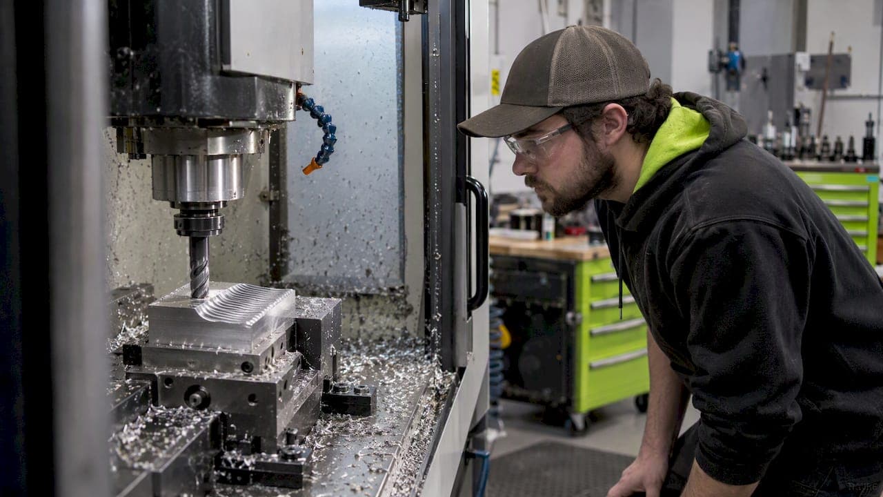
Milling chatter is a self-excited regenerative vibration that forms when a cutting edge re-encounters the wavy surface left by the previous tooth pass. Stop it right now by shortening tool stickout, nudging spindle speed up or down by a few percent, cutting depth of cut, and rechecking the toolholder clamp. Those four moves resolve most chatter before you touch a sensor or a stability chart.
TL;DR:
- Shortening tool stickout, slightly adjusting spindle speed, and checking toolholder clamp tension can resolve most chatter issues quickly.
- Changing spindle speed by 3 to 5 percent often breaks chatter cycles, especially when combined with mechanical fixes like tool overhang reduction.
- Stability lobe diagrams help identify safe speed and depth of cut zones, but mechanical adjustments usually outperform complex modeling for quick fixes.
- Chatter produces a rising buzz or rattle and segmented chips, with detection improved by monitoring spectral peaks near structural mode frequencies.
- Mechanical solutions, like fixing tool runout and improving workholding, should be exhausted before considering advanced instrumentation or active damping.
What causes milling chatter and why it matters
Regenerative chatter starts with a small disturbance, a hard spot, a slight deflection, a momentary loss of contact. The next tooth to pass over that same surface meets an uneven cut, and the resulting force variation feeds back into the tool-workpiece system with a phase lag relative to the previous pass. When that lag lines up with the system's natural frequency, the vibration grows instead of damping out. This feedback loop is widely identified as the dominant mechanism limiting material removal rates in milling.

The practical fallout shows up fast. Surface finish develops a visible wave pattern, often with a telltale ripple spacing tied to the chatter frequency. Tool wear accelerates because the edge is taking inconsistent bites instead of a steady chip load, and in severe cases the edge chips or fractures outright. Noise climbs sharply, often to a harsh buzz or scream. And because the only reliable way to quiet unstable chatter is to back off depth of cut or spindle speed, every chatter event costs you material removal rate, which is the metric that drives cycle time and shop throughput.
How to spot chatter on the shop floor
Chatter has a distinct signature that separates it from ordinary runout or forced vibration from an unbalanced holder. Runout tends to produce a steady, periodic mark tied directly to spindle rotation. Chatter sounds different: a rising buzz, squeal, or rattle that often builds over a second or two rather than staying constant from the first contact.
- Listen for a tone that grows, not one that is present at full strength the instant the cut starts.
- Feel the machine structure, not just the spindle; chatter often shows up as a buzz in the column or table, while forced vibration stays localized near the spindle.
- Look at the chip, since chatter frequently produces segmented or variable-thickness chips instead of a continuous ribbon.
- Check the finish pattern, where regenerative marks repeat at a spacing unrelated to feed per tooth, unlike a forced-vibration mark that tracks feed rate exactly.
Accelerometers, cutting-force dynamometers, acoustic emission sensors, and even spindle current or encoder signals can all flag chatter, and research on detection methods consistently points to a spectral peak near the dominant structural mode, often with sidebands around the tooth-passing frequency, as the clearest indicator; multi-sensor fusion with signal processing improves reliability over any single channel, according to a review of chatter detection methods. On the floor, the fastest diagnostic is still a quick test cut: change feed rate and watch whether the noise tracks it (forced vibration) or stays put (chatter), then try a small spindle speed change and see if the tone shifts or disappears.
Stability lobe diagrams and the dynamics behind chatter
A stability lobe diagram (SLD) plots axial depth of cut against spindle speed, with stable and unstable zones mapped as scalloped lobes rather than a flat line. The lobes exist because stability depends on the phase relationship between the tooth-passing frequency and the structure's natural frequency, and that relationship repeats at specific spindle speed bands. Pick a speed inside a lobe peak and you can often run a deeper cut than a neighboring speed would allow, which is why two seemingly similar spindle speeds can behave very differently in the cut.
Building an SLD starts with a frequency response function (FRF), usually gathered through impact or modal testing of the tool-holder-spindle assembly. That FRF captures stiffness, damping, and effective mass at the tool tip, the three properties that set where the lobes sit. A longer, lighter tool behaves differently than a short, heavy one, and swapping holders shifts the whole diagram. Newer robustness-augmented and 3D versions of the SLD extend the classic model to include radial depth of cut and account for uncertainty in the modal parameters, which helps shops avoid picking a speed that looks stable on paper but sits right at a fragile lobe boundary, as described in work on robustness-augmented stability lobe diagrams.
Stability is not fixed for the whole job, either. As a part is roughed out, wall thickness drops and stiffness changes, so a cut that was stable at the start can go unstable as material is removed, a concern covered in our slot machining guide for thin-wall and slot work.

How to prevent and suppress milling chatter
Start cheap and work up. Most chatter problems resolve with mechanical changes that cost nothing but setup time.
- Shorten tool stickout first; reducing overhang is one of the single biggest stiffness gains available on the floor.
- Switch to a stiffer or shorter toolholder, and confirm runout is within spec before blaming dynamics.
- Improve workholding and support, adding a backstop, extra clamp, or dovetail fixture where the part can flex, a topic covered in our dovetail workholding guide.
- Try a variable-pitch or variable-helix cutter, which disrupts the regular timing that regenerative chatter depends on.
- Reduce axial or radial depth of cut, then rebuild toward target stock removal once the cut is quiet.
- Nudge spindle speed, including small modulation rather than a single fixed RPM, since encoder-based control research shows that varying speed in real time can break the feedback loop.
Tool-holder geometry has more leverage than most machinists expect. Receptance Coupling Substructure Analysis (RCSA) and structural modification methods let a shop predict how a new holder diameter or a tunable-mass holder will shift the stability lobes without testing every geometry by hand, since structural modification of tool-holder geometry can move the usable speed range toward where you need to run. Increasing overall rigidity everywhere is rarely the cheapest fix; tuning holder mass or tool length to shift a lobe is often faster and less expensive.
When passive changes do not fully solve it, active and semi-active options exist: tuned-mass dampers absorb energy at the problem frequency, smart spindles and encoder-feedback systems detect chatter energy and adjust speed automatically, and some controllers now run this suppression in real time rather than as an offline correction.
Pro Tip: Before buying any active damping hardware, try a 3 to 5 percent spindle speed change first. It costs nothing and resolves a surprising share of chatter on its own.
Escalate to instrumented FRF testing or modal analysis only when mechanical fixes and speed changes fail repeatedly on the same setup; that is the point where guessing stops paying off.
Shop troubleshooting checklist for chatter
- Stop and listen for a rising tone versus a steady one, and note whether it tracks feed rate.
- Tighten the toolholder and retest; a loose collet or worn taper causes chatter that mimics dynamic instability.
- Shorten stickout to the minimum length the feature allows, then rerun the cut.
- Change spindle speed by 3 to 5 percent, up or down, and watch whether the tone shifts or clears.
- Reduce depth of cut, axial first, then radial, until the cut quiets, then rebuild gradually.
- Run a quick sensor check if available: a clear spectral peak near a structural mode with sidebands at tooth-passing frequency confirms regenerative chatter rather than runout.
- Instrument the machine with impact testing if steps one through six do not resolve it on a repeat job, since that points to a structural issue worth mapping on an SLD.
- Consider active suppression (tuned dampers, encoder-based speed control) only after the cheaper steps have been exhausted.
This escalation order, cheap mechanical checks first, then instrumentation, then active suppression, matches the sequence recommended in research on real-time chatter detection and spindle speed control.
Why most chatter fixes fail before they start
Most chatter advice online jumps straight to stability lobe diagrams and modal testing, which is backwards for the vast majority of shop floor cases. Reaching for instrumentation before checking stickout, clamp torque, and holder runout wastes time on expensive diagnostics for a problem a wrench would have fixed. The honest order of operations is cheap and mechanical first, dynamic and instrumented second.
The other mistake is treating "more rigid" as the universal answer. Rigidity helps, but tuning what you already have, tool length, holder mass, spindle speed, often moves a cut from an unstable lobe into a stable one faster than sourcing a heavier setup ever will. Chatter is a timing problem as much as a stiffness problem, and shops that only chase stiffness miss half the lever.
— Drake
How Flying Chip Factory handles chatter in prototype and short-run work
On prototype and short-run jobs, we lean on the same low-cost fixes first: shortest practical stickout, a fixture built for the specific part rather than a generic vise setup, and small spindle speed adjustments before anything else. Thin-wall and bracket work gets extra attention to stiffness changes as material comes out, which we cover in our slot machining guide and our tight tolerance machining guide. Feature choices matter too, since thread milling instead of tapping can reduce chatter risk near thin walls, a tradeoff we break down in our thread milling vs. tapping guide.
When a shop can solve chatter faster than a formula
If you would rather hand a part to a shop that already runs this checklist than chase stability lobes yourself, that is exactly the kind of work we take on. We machine prototype parts, short-run production, and custom fixtures, brackets, and support parts directly, with the same person designing, machining, and shipping the job handling your questions.

We also apply this same process discipline to our own products, including the E2 Kickstand for the KTM SX-E 2, GASGAS MC-E 2, and Husqvarna EE 2, machined in-house rather than outsourced. If your next part is fighting chatter on someone else's machine, send us the geometry and we will quote the job.
FAQ
What is milling in a lathe machine?
Milling on a lathe typically refers to live tooling or a mill-turn setup, where a rotating cutter performs milling operations, such as slotting or drilling off-center, while the part is held in the lathe's spindle or a sub-spindle. It differs from conventional milling, where the cutter moves and the part stays fixed in a vise or fixture.
What are the hazards of using a milling machine?
Common hazards include contact with rotating cutters and spindles, flying chips, workpiece ejection from inadequate clamping, and noise exposure from chatter or normal cutting. Loose clothing, unsecured long hair, and missing guards around the cutting zone are frequent causes of injury.
What does machine tooling mean?
Machine tooling refers to the cutting tools, toolholders, fixtures, and work-holding devices used to shape a part on a machine tool. It includes everything from the end mill and collet to the vise, clamps, and custom fixtures that position and secure the workpiece.
What does CNC chatter sound like?
CNC chatter typically sounds like a buzz, squeal, or rattle that builds in intensity over a second or two rather than staying constant from the moment the tool engages. It is often accompanied by a visible wavy pattern on the machined surface and segmented or inconsistent chips.
Sources
- Chatter overview and regenerative chatter explanation
- Chatter detection in milling processes — review on signal processing and condition classification
- Chatter avoidance via structural modification of tool-holder geometry
- Real-time milling chatter detection and control with axis encoder feedback and spindle speed manipulation