
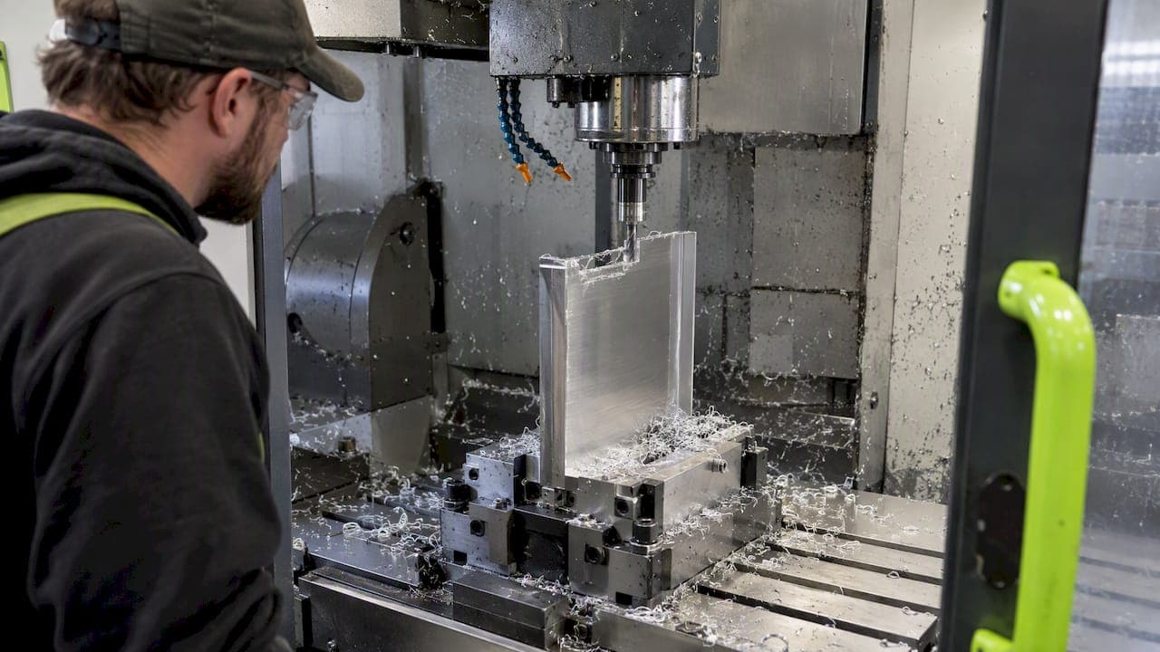
The best approach to thin wall machining combines layered staircase finishing, engineered fixturing or auxiliary support, and conservative finishing parameters with active monitoring. At Flying Chip Factory, this combination is what keeps thin-walled prototypes and short-run parts in tolerance, and it lines up with recent findings that feed rate alone can account for most of the measured wall deformation in high aspect-ratio walls. The tactics below cover toolpaths, fixturing, tooling, and parameter selection in that order.
TL;DR:
- Staircase finishing preserves support by cutting horizontal layers; level first sequencing and extra stock on tall, unsupported sections further reduce vibration and deflection.
- Above a height to thickness ratio of 20, feed rate explains about 87% of deformation; reduce it first when deflection appears.
- Modal testing can locate support points; correctly placed auxiliary supports have raised natural frequency by 8–13%, but they complement rather than replace conservative cutting parameters.
- Choose a short, rigid carbide end mill with minimal overhang; variable pitch geometry and climb milling can reduce chatter, but test each setup.
- If feed and depth adjustments fail within two or three test passes, redesign support placement and measure dimensions after cooling.
Why Thin Walls Are Unstable: Deformation Drivers and What to Control
A thin wall loses stiffness as material is removed, and that stiffness keeps changing throughout the cut. Early passes cut through a relatively rigid blank, but by the final finishing pass, the wall behaves like a flexible plate that deflects under the same cutting force that barely moved it an hour earlier. That shifting compliance is what sets up regenerative chatter: the tool leaves a wavy surface, the next pass cuts into that wave, and the vibration amplitude grows instead of settling.
Height-to-thickness ratio is the single number worth tracking here. Research on micro-milling thin walls found that once the h/t ratio climbs past 20, feed rate becomes the dominant factor driving deformation, while depth of cut mainly governs tangential cutting force. Cutting temperature adds another layer: thermomechanical interactions between heat buildup and cutting force influence post-machining deformation, which is why a wall that measures in spec right off the machine can bow slightly after it cools.
This is why a rough, semi-finish, finish sequence matters more on thin walls than almost anywhere else in a machining plan. Each stage needs to respect how much stiffness remains before committing to the next set of parameters.
Toolpath and Allowance Strategies: Staircase, Level-First, and Non-Uniform Stock
Staircase, or waterline, finishing cuts a thin wall in horizontal layers from the top down, or bottom up, rather than tracing the full height in one pass. Each layer keeps a band of uncut material supporting the section still being machined, so the tool is never working against the most flexible possible geometry. Industry practice treats layered finishing as the most effective professional strategy for tall thin walls, a conclusion echoed in reviews of cutting-parameter optimization for this exact problem.
Level-first toolpaths, where every region at a given height finishes before the tool drops to the next level, outperform region-based approaches on tall or irregular walls because they avoid leaving one thin section unsupported while another section is still being roughed nearby. Pairing that with non-uniform allowance, leaving more stock where the wall is tallest or least supported and less where it is backed by adjacent structure, lets the toolpath match the stiffness map of the actual part instead of treating every wall segment the same. Shops that adopt this combination report meaningful gains: tailoring toolpaths to a part's changing compliance can more than double productivity while cutting vibration amplitude by roughly half and surface roughness by about a third compared to uniform-allowance strategies.
A practical CAM checklist for staging these passes:
- Set layer thickness based on the wall's local h/t ratio, thinner layers where the ratio is highest.
- Leave extra non-uniform stock on the tallest or least-supported sections identified during stiffness analysis.
- Reduce spindle speed slightly between layers as unsupported height increases, rather than holding one speed for the whole wall.
- Finish one side of a wall while the opposite side stays bulk-supported, a sequencing approach common in professional shop practice that avoids thinning both faces at once.
Pro Tip: Simulate the toolpath against a stiffness model before cutting; a layer that looks fine in isolation can still hit a compliance cliff if the previous layer removed more support than expected.
Fixturing, Auxiliary Supports, and Damping for Dynamic Stiffness
Clamping alone rarely solves a thin-wall chatter problem, because the issue is usually stiffness at the point of cut, not stiffness at the workholding interface. A quick modal or hammer test, tapping the part and reading the response, identifies which sections carry the highest vibration amplitude so auxiliary supports go exactly where they matter instead of wherever is convenient. Our modular fixturing guide covers setup layouts that work well as a starting point for this kind of support planning, and our dovetail workholding guide adds clamping detail for repeatable setups.
Auxiliary support module placement, informed by that modal data, can raise system natural frequencies meaningfully: documented examples show fundamental frequency increases of 8 to 13 percent or more once supports are positioned at the right nodes. Damping options scale with the problem:
- Passive options like tuned mass dampers, viscoelastic pads, and sacrificial stiffeners add rigidity without machine modifications.
- Semi-active and active damping systems adjust stiffness or resistance in real time and suit higher-value or recurring thin-wall jobs.
- A comprehensive review of chatter suppression confirms that passive, semi-active, and active strategies all measurably expand the stable cutting region in thin-wall milling.
For a small shop running a one-off prototype, sacrificial ribs left in the stock, temporary clamps near the highest-amplitude zone, and viscoelastic backing pads during the final finishing pass usually close most of the gap without a dedicated damping fixture.
Pro Tip: Place auxiliary supports at the antinodes identified in your modal test, not at the geometric midpoint; a support placed by eye often misses the section actually driving the vibration.

Tooling and Cutting Strategy for Reduced Deflection
Cutter choice and engagement strategy do as much work as the toolpath itself. A short, rigid tool with minimal overhang, paired with variable-pitch or variable-helix geometry, breaks up the regular tooth-passing frequency that feeds regenerative chatter. Our slot machining guide covers short-reach tooling and step-down logic that transfers directly to thin-wall finishing.
Practical selection points:
- Favor a solid carbide end mill with the shortest practical flute length over a ball-nose profile unless the wall geometry genuinely requires a ball profile.
- Keep radial engagement low on finishing passes, often in the single digits as a percentage of tool diameter, to limit deflection force against the flexible wall.
- Climb milling generally produces a cleaner finish and lower deflection tendency on thin walls than conventional milling, though both should be tested against the specific setup.
- On micro-milling jobs, watch for ploughing at very low chip thickness: below the minimum chip thickness, the tool rubs and burnishes instead of shearing cleanly, which raises forces and heat instead of reducing them.
Matching tool stiffness to wall stiffness, rather than defaulting to whatever cutter finished the last job, is often the difference between a clean final pass and a wall that chatters right at the top of its height.
Process Parameters and Stability: Turning Research into Shop Rules
Feed rate, depth of cut, and spindle speed interact differently depending on how tall and thin the wall already is, so a single "safe" recipe does not transfer across jobs. The clearest data point here comes from micro-milling research on thin walls with h/t ratios above 20: feed rate accounts for roughly 87 percent of measured wall deformation, while depth of cut drives about 57 percent of the tangential cutting force. That split tells a shop where to spend its caution: dial back feed rate first when a tall thin wall starts showing deflection, and treat depth of cut as the lever for controlling force rather than finish quality.
A workable parameter routine:
- Start finishing passes with a conservative chip load well below the rough-machining value, then increase incrementally while watching the part, not the spindle load meter alone.
- Hold spindle speed in the stable region identified by test cuts rather than the highest speed the tool rating allows; stability lobes shift as the wall thins, so a speed that was stable at roughing height may not stay stable at finish height.
- Reduce depth of cut on the final pass once wall thickness drops below roughly 1.5 millimeters, since walls at or above that thickness can tolerate maximum axial depth of cut only when speed and stability are already controlled.
Feed rate dominates deformation risk on tall thin walls: in high h/t micro-milling, feed rate explains about 87 percent of measured wall deflection, making it the first parameter to adjust when a wall starts moving out of tolerance.
Watch for a dull, rubbing sound or a burnished rather than cut finish, both signs of ploughing at too low a chip load. If adjusting feed and depth does not stabilize the cut within two or three test passes, pause and redesign the support layout rather than chasing parameters further.
Shop-Proven Workflow and Checklist From Flying Chip Factory
Thin-wall jobs typically follow a consistent sequence: rough the blank leaving uniform stock, re-check stock condition before semi-finishing, stage finish passes in layers from the most supported section outward, and inspect critical dimensions immediately after machining and again after the part reaches room temperature.
Before sending a thin-wall part to any shop, including ours, have ready:
- A STEP file with wall thickness and height called out explicitly, not just implied by the model.
- Critical tolerances flagged separately from general dimensions, so finishing passes get the attention they need.
- Material and surface finish requirements stated up front, since both affect parameter selection.
- Any known problem areas from prior attempts, including where chatter or distortion showed up before.
Our tight tolerance machining guide outlines the inspection checkpoints we apply at final sign-off.
Why We Favor Stability-First Methods on Thin Walls
Conservative finishing parameters cost a little cycle time up front, but they cut rework and scrap dramatically on short-run prototype work, where a single warped wall can mean restarting the whole job. Having direct machinist access, instead of routing changes through layers of account management, lets adjustments to a toolpath or support layout be made quickly when a problem shows up, which matters most on tricky thin-wall jobs where guesswork is expensive.
— Drake
Getting Your Thin-Wall Parts Machined Right the First Time
Prototype machining, short-run production, and fixture or bracket fabrication are performed in the same shop, with no sales layer between customers and the machinist cutting their parts. For a thin-wall job, a quick consult before the first pass often catches a fixturing or allowance problem that would otherwise show up as a warped part on the inspection table.

To get an accurate quote, send us:
- A STEP file with wall thickness, height, and critical tolerances called out.
- Your target material and required surface finish.
| What to send | Why it matters |
|---|---|
| STEP file with wall dimensions | Lets us plan layer thickness and support placement before cutting |
| Material and finish spec | Drives feed, speed, and depth of cut decisions |
| Known tight tolerances | Flags which sections need staged, conservative finishing |
If you want to see finished work before committing, our E2 Kickstand for KTM SX-E 2, GASGAS MC-E 2 & Husqvarna EE 2 shows the fit and finish standard we hold on our own in-house parts. Reach out through our prototype and short-run services page to get a quote started.
FAQ
What is thin wall machining in CNC manufacturing?
Thin wall machining refers to cutting walls or features where thickness is small relative to height, making the section prone to deflection and vibration during cutting. It requires specific toolpath, fixturing, and parameter choices rather than standard machining practice.
What height-to-thickness ratio makes a wall difficult to machine?
Once the height-to-thickness ratio climbs past 20, feed rate becomes the dominant driver of wall deformation rather than depth of cut. Below that ratio, walls generally behave closer to standard features and tolerate more aggressive parameters.
How does staircase or waterline finishing help thin walls?
Staircase finishing cuts a wall in horizontal layers so a band of uncut material always supports the section currently being machined. Industry practice treats this layered approach as the most effective strategy for tall thin walls.
Can auxiliary supports replace the need for careful parameters?
No, auxiliary supports raise the part's natural frequency and reduce vibration, with documented gains of 8 to 13 percent in key modal frequencies, but they work alongside conservative feed and depth choices, not instead of them. Both the fixturing and the parameter side need attention for a stable cut.
Does Flying Chip Factory machine thin-walled prototype parts?
Yes, prototype machining and short-run production are core services, and thin-wall jobs are handled with staged finishing and fixturing planned around each part's geometry. Pricing is quoted per project since wall geometry and material vary.
Sources
- Optimization of Cutting Parameters to Minimize Wall Deformation in Micro-Milling of Thin-Wall Geometries
- A review of chatter suppression in thin-wall milling: strategies, mechanisms, and applications