
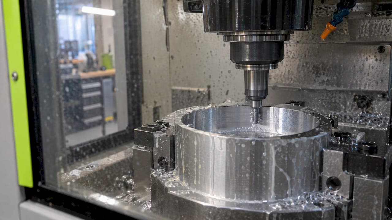
Tool deflection is the lateral bending of a cutting tool under cutting force, and the single biggest lever for controlling it is minimizing stickout while using the largest diameter cutter the job allows. Shorter overhang and a bigger core diameter cut deflection faster than any other adjustment. How much deflection you can tolerate depends on whether you are roughing or finishing.
TL;DR:
- Finishing passes should stay below 0.0005 inches, roughing can tolerate 0.002 inches, and sealing surfaces or press fits may need 0.0002 inches.
- Doubling stickout increases deflection roughly eightfold, while doubling cutter diameter makes the tool roughly sixteen times stiffer under the same cutting load.
- CAM and FEA estimates can miss by nearly 20% without calibration, so confirm planned settings with a test cut before production.
- Check holder clamping and runout before changing cutting parameters; poor fit or fixture flex can remain the cause even when the cutter appears stiff.
What Tool Deflection Is and the Physics Behind It
A cutting tool held in a spindle behaves like a cantilever beam: fixed at one end, loaded at the other by cutting forces. Deflection grows with the cube of stickout length and shrinks with the fourth power of diameter, a relationship detailed in endmill deflection analysis. That L^3 over d^4 sensitivity means small changes in either variable produce outsized results.
Diameter matters most at the core, not the cutting edge. For a fluted endmill, the flute valley diameter (the thinnest cross section) governs stiffness, so using the nominal cutting diameter in a rigidity estimate understates real deflection, according to the same endmill deflection analysis.
System compliance adds on top of tool bending. Spindle play, holder fit, and fixture rigidity all flex under load, and machine structural stiffness is often the part designers and machinists overlook when a part comes out of tolerance despite a stiff-looking tool.
How Deflection Affects Part Quality, Tool Life, and Process Stability
Deflection shows up first as dimensional drift: holes bore oversize, walls taper, and pockets lose their programmed corners because the tool pushes away from the cut instead of holding its line. On the surface, that same bending triggers chatter, leaving rippled or chattered finish where a straight wall was programmed.
Tool life takes a hit too. A deflected tool rubs instead of cutting cleanly on part of its engagement, and that uneven load adds to the wear already caused by runout, shortening edge life faster than either factor alone would.
Finishing passes typically target deflection under 0.0005 inches (0.013 mm), while roughing can often tolerate up to 0.002 inches (0.05 mm). That gap matters: a setup that is perfectly fine for stock removal can ruin a finish pass if nothing changes between operations.
Tighter work, like sealing surfaces or press-fit bores, often needs deflection held closer to 0.0002 inches (0.005 mm), a threshold worth knowing before you commit a job to a single setup. For more on matching deflection limits to part tolerances, see our tight tolerance machining guide.
How to Calculate and Estimate Expected Deflection
The basic deflection formula is Δ = (constant) × F × L³ / (E × I), where F is cutting force, L is stickout length, E is the tool material's stiffness, and I is the moment of inertia from the core diameter. You do not need to solve it precisely to use it. The exponents tell the story: L is cubed and diameter (through I) is raised to the fourth power.
Doubling stickout multiplies deflection roughly 8 times, and doubling tool diameter makes the tool roughly 16 times stiffer under the same load, per the endmill deflection analysis. That is why a quarter-inch extra reach hurts more than most operators expect, and why swapping to the next size up in diameter is usually more effective than any feed or speed adjustment.
Recommended working thresholds: finishing around 0.0005 in (0.013 mm), roughing up to about 0.002 in (0.05 mm), and precision-critical work down near 0.0002 in (0.005 mm).

How to Measure or Detect Deflection in the Shop
Instrumented measurement gives the clearest picture. Sensory toolholders and rotating dynamometers, such as the Kistler Type 9171A, capture bending moments and multi-axis cutting forces directly, which is valuable when optimizing a recurring high-value job, as described in sensory holder research on drilling performance. That level of hardware is rarely justified for a one-off prototype.
Most shops get useful answers without it. A spring pass (recutting the same path at the same depth and checking whether the part moves) reveals how much the tool pushed away on the first pass. Comparing a finished dimension against the programmed depth, or running an on-machine probing check, does the same job with equipment most shops already own.
CAM and FEA deflection estimates are useful for planning, but published models can run error margins near 20% without calibration against real cuts, so treat simulation as a starting point and confirm with an actual test cut before committing a production run.
Practical Ways to Reduce and Control Tool Deflection
Geometry changes give the biggest return. Cut stickout to the minimum the feature allows, step up to the largest diameter the pocket or hole permits, and favor long-reach tools, which keep a larger neck diameter, over long-flute tools when rigidity matters more than chip clearance, per the tool deflection countermeasures guidance. Long-flute tools still earn their place in deep, narrow cavities where chip evacuation is the limiting factor, but accept the deflection trade-off there rather than fighting it with speed changes.
Tooling and fixturing come next. Shrink-fit and hydraulic holders clamp tighter than standard collets, which measurably reduces system compliance. Check clamping length against the manufacturer's spec, confirm the holder bore finish and hardness, and verify runout before blaming the tool for a finish problem. Fixture rigidity deserves the same scrutiny; our dovetail workholding guide covers clamping choices that reduce part movement under load.
Cutting strategy rounds it out. Match depth of cut and stepover to the tool's actual stiffness rather than a catalog recommendation, and reserve a light spring pass for the final finishing cut. Climb milling tends to push the tool into the cut and can help control deflection direction on finishing passes, while conventional milling suits roughing where tool life matters more than finish. For slots and other deep features, high-efficiency milling strategies covered in our slot machining guide keep radial engagement low enough to limit deflection without sacrificing material removal rate.
When a part's tolerance leaves no margin for error, active force sensing or outsourcing to a shop with the tooling and experience to dial in the setup is often faster than iterating alone.
Shop-Ready Decision Checklist and Verification Steps
Run through this order whenever a part comes out tapered, oversize, or chattered:
- Inspect toolholder clamping and check runout before changing anything else.
- Minimize stickout to the shortest length the feature geometry allows.
- Upsize the cutter diameter if the feature can accept it.
- Reduce depth of cut or stepdown to lower cutting force.
- Run a spring pass or an on-machine probe check against the programmed dimension.
- Confirm finish and tolerance meet spec before releasing the part.
If the result still misses tolerance after these steps, the fixture or holder, not the cutting parameters, is usually the real problem. For chatter that persists despite these fixes, our milling chatter fixes article covers additional shop-tested adjustments. Beyond that point, a specialist shop with calibrated tooling and deflection data on hand will solve it faster than continued trial and error.
A Machinist's View From the Flying Chip Factory Floor
We build precision parts for electric mini dirt bikes and take on prototype and short-run jobs for outside customers, which keeps deflection a constant, practical concern rather than a textbook topic. A common fix in our shop: a bored hole was coming in oversize and tapered, and switching from a long-flute endmill to a long-reach tool with the same stickout, paired with a shrink-fit holder, brought the bore back within tolerance without touching feeds or speeds.
That kind of fix is often faster than reworking a program, and knowing when to make it in-house versus handing the job to a shop with the right tooling on hand saves time either way.
The Overrated Fix and the One That Actually Works
Most troubleshooting advice leads with feeds and speeds: slow down, take a lighter cut, add a pass. That approach treats the symptom. Cutting force still bends the tool the same way per unit of load, and a lighter cut just extends the time spent fighting a geometry problem instead of fixing it.
The formula makes the priority obvious. Stickout and diameter dominate the deflection equation by orders of magnitude more than force does, so a shop that chases speeds and feeds before checking overhang and cutter size is optimizing the wrong variable. The core diameter detail gets skipped most often: a tool that looks rigid by its cutting diameter can still flex badly if its flute valley is thin, and that gap between advertised size and real stiffness explains a lot of unexplained chatter.
If there is one habit worth building, it is measuring stickout before touching the control panel. Everything else, holder choice, cutting strategy, even material selection, works better once overhang is already minimized.
— Drake
How Flying Chip Factory Supports Deflection-Sensitive Jobs
When a part's tolerance leaves no room for guesswork, prototype machining, short-run production, and custom fixtures, brackets, and support parts can be built around the same deflection principles covered here. Working directly with the machinist who designs and builds each job means tooling and holder choices get dialed in fast, without a sales layer slowing down revisions.

If overhang, holder rigidity, or cutter selection is holding up a job, request a quote for prototype or short-run machining and we will work through the setup with you directly.
FAQ
How much tool deflection is acceptable?
Acceptable deflection depends on the operation: finishing passes generally target under 0.0005 inches (0.013 mm), while roughing can often tolerate up to 0.002 inches (0.05 mm). Precision-critical work may require deflection held closer to 0.0002 inches (0.005 mm).
How do you calculate tool deflection?
Deflection follows Δ = (constant) × F × L³ / (E × I), where stickout length (L) and core diameter (through I) dominate the result far more than cutting force does. Doubling stickout raises deflection roughly 8 times, and doubling diameter makes the tool roughly 16 times stiffer under the same load.
What does tool deflection mean in machining?
Tool deflection is the lateral bending of a cutting tool away from its programmed path, caused by cutting forces acting like a load on a cantilever beam. It leads to oversize dimensions, tapered walls, chatter marks, and reduced tool life when left unchecked.
What tools are used to measure tool deflection?
Shops with the budget for direct measurement use sensory toolholders and rotating dynamometers, such as the Kistler Type 9171A, which capture cutting forces and bending moments. Most shops instead rely on spring passes, on-machine probing, and comparing finished dimensions against programmed depth.