
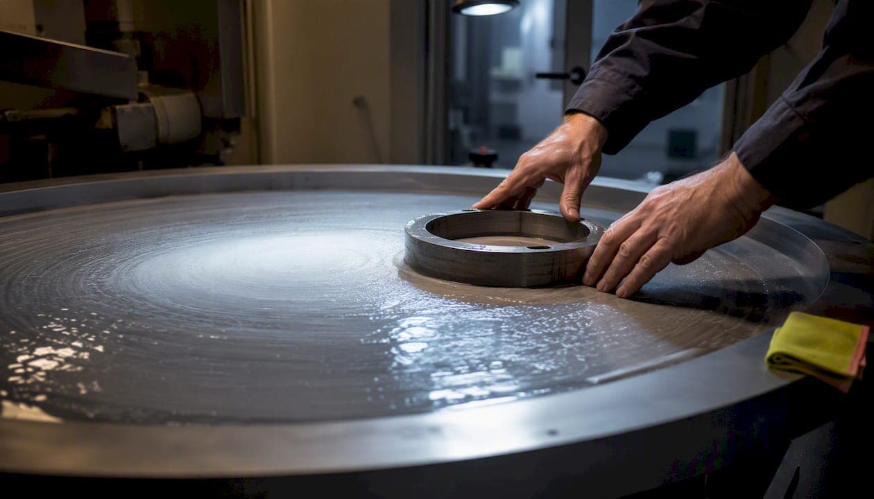
Lapping is the finishing process that produces the tightest flatness a machine shop can hold, often down to a few tenths of a micron, but only if the lap plate itself is flat and the process is verified with the right measurement method. Skip plate inspection and you are not lapping the part. You are copying whatever error is already sitting in the plate. Before chasing abrasive grades or dwell times, measure the plate with an optical flat or dial indicator setup and correct its profile first.
TL;DR:
- Flatness achievable by lapping depends on plate control and can reach a few tenths of a micron, but only if the plate is correctly measured and maintained.
- Plate inspection should use simple tools like optical flats or dial indicators, with regular re-measurement to prevent wear-induced errors like concavity or convexity.
- Abrasive selection and grit progression are critical; finer grains and gradual reduction prevent surface scratches and improve flatness without sacrificing removal rate.
- Proper fixturing and adjustable conditioning rings, along with measured feedback, are essential for maintaining a flat lap plate over time.
- Accurate flatness verification must match the required tolerance, using appropriate measurement tools, sampling points, and logging practices to catch failures early.
What Lapping for Flatness Actually Fixes in a Precision Workflow
Grinding removes material fast and gets a part close to size. Lapping is the slower step after that, cleaning up the last few microns of form error and leaving a controlled surface texture. Comparative process writeups on precision grinding versus lapping describe this pairing plainly: grinding builds bulk shape, lapping perfects flatness and parallelism once the shape is roughly right. Trying to lap out a part that is still 0.005 inches out of flat wastes abrasive and time you should have spent on the grinder.
Flatness tolerances achievable by lapping typically run from a few tenths of a micron up to a handful of microns across the part, depending on span, material, and how tightly the plate is controlled. That range matters because it defines what "good enough" looks like before you even touch a gauge. Gauge blocks, seal faces, hydraulic valve plates, and optical mounts routinely call for this level of control, and grinding alone rarely gets there consistently.
Flatness callouts on a drawing also get misread more often than any other GD&T symbol. A few things worth locking down before the job starts:
- Flatness controls the surface itself, independent of any datum. Parallelism controls that same surface relative to a reference. Confusing the two leads to inspecting the wrong thing.
- Flatness is a minimum-zone envelope fit under ASME and ISO standards. A least-squares fit, which some CMM software defaults to, can overstate flatness by 30 to 50 percent compared to the correct minimum-zone method.
- If the drawing does not explicitly call flatness, do not assume it. Confirm with engineering before quoting a lapping operation nobody actually specified.
For a deeper look at when to call one versus the other, flatness versus parallelism breaks down the practical difference on real drawings.
How Do You Measure and Maintain Lap Plate Flatness?
Picture the lap plate as a mirror image stamped into every part that touches it. A plate with a slight dome will lap a part convex. A plate worn concave in the middle will leave a part with a raised edge and a sagging center. The part cannot fix what the plate already did to it.
Checking plate geometry does not require exotic equipment for most shop work. Three methods cover nearly every situation:
- Straight edge and feeler gauge for a fast go/no go check between production runs.
- Dial indicator on a surface plate, sweeping the lap plate radially, gives roughly 2 to 5 micron resolution and works fine for routine monitoring.
- Optical flat with monochromatic light for anything approaching sub-micron work, where fringe counting reveals wear patterns a dial indicator would miss entirely.
Once you know the profile, correction comes down to conditioning ring repositioning, redressing the surface, or, when wear has gone too far, resurfacing or replacing the plate outright. A plate that has gone concave in the center from years of inner-track wear is not something you dress your way out of forever.
Pro Tip: Log every plate reading against part span. A plate that passes for a 2-inch part can still ruin a 12-inch part, because deviation scales with the diameter being lapped, not the plate's overall condition.
As a rough acceptance guideline, plate deviation should stay under roughly 10 to 20 percent of your target part tolerance across the span you are actually lapping. Tighter parts need tighter plates, not just more patience.
Choosing Abrasives and Media That Actually Improve Flatness
Abrasive choice affects flatness indirectly, through material removal rate and how evenly that removal happens across the part. Diamond abrasive cuts fastest and holds its grade longest, making it the default for hardened steels and carbides. Silicon carbide is cheaper and works well on softer steels and cast iron. Aluminum oxide sits in between, often used on softer non-ferrous materials where diamond would be overkill.
Slurry, paste, and emulsion carriers each trade off differently:
- Slurry (loose abrasive suspended in oil or water) gives the fastest material removal rate but the roughest control over consistency.
- Paste holds concentration more predictably and suits lower-volume, higher-precision jobs.
- Emulsion blends and cools well for extended runs but generally trades some removal rate for that stability.
Material removal rate in lapping is inherently low compared to grinding, and it depends heavily on applied pressure, relative velocity, abrasive concentration, and grain size. Finer grains improve finish but cut removal rate further, which is exactly why finish-lapping passes use progressively finer grit and lighter pressure rather than trying to rush the last pass.
Pro Tip: Step abrasive grades down gradually, not in one jump. Going straight from a coarse grade to a mirror finish grade tends to leave scratch patterns the fine abrasive cannot fully remove, because it never actually contacts the deepest coarse scratches.
Fixturing matters just as much as abrasive selection. A holder that concentrates pressure at the part's edge causes edge rounding, the classic symptom of a rigid fixture on a part that needs to float slightly with the plate.
Using Conditioning Rings and Speed to Steer Plate Wear
Plate wear is not uniform across the radius, and that unevenness is actually useful once you understand it. Kinematic research on single-plate lapping shows that conditioning ring position and rotational speed changes can be used deliberately to correct or maintain plate profile, not just to hold parts in place during the cycle.
The practical rule shops use: move the conditioning ring outward to reduce wear at the plate's inner diameter, correcting a plate that has gone concave. Move it inward to reduce outer diameter wear, correcting a convex plate. Relative rotational speed between the plate and the conditioning ring changes how evenly abrasive contact distributes across the radius, so speed and ring position work together, not separately.
A corrective cycle follows a repeatable sequence:
- Measure current plate profile with an optical flat or dial indicator sweep.
- Identify whether the plate is running convex or concave and by how much.
- Reposition the conditioning ring and adjust relative speed based on that reading.
- Run a controlled lapping cycle, tracking hours or part count, not just time on the clock.
- Remeasure and compare against the previous reading before releasing the plate back to production.
Treat this as a feedback loop, not a one-time fix. Plates drift again after enough cycles, and the correction that worked last month will not hold forever without rechecking.
What's the Right Way to Verify Flatness After Lapping?
Measurement method should match your tolerance, not your habit. An optical flat under sodium light delivers roughly 0.05 to 0.1 micron resolution. A CMM typically resolves 0.5 to 2 microns. A dial indicator on a surface plate lands around 2 to 5 microns, which is plenty for many production tolerances and a lot cheaper to run shift after shift.

For sub-micron work, the optical flat and monochromatic light method is still the standard because it is fast and inexpensive relative to CMM scanning. Sodium light has a wavelength of 589 nanometers, and each dark fringe you count represents about 294 nanometers of height difference. Count dark bands only. Counting both light and dark bands doubles your calculated deviation and hands you a false failure or a false pass, depending on which way the error runs.
Sampling density matters more than most shops assume. A handful of readings near the center will miss edge roll-off every time.
On sampling: industry practice calls for 25 to 36 measurement points across a 300 millimeter surface to reliably catch localized warp, well above the 9-point floor commonly used on small parts.
Skipping points near the edges is the single most common way flatness failures slip through inspection undetected.
Building a Log and Troubleshooting Routine That Catches Failures Early
Inspection frequency should scale with production volume and tolerance width. High-volume, loose-tolerance work might only need a daily plate check. Tight-tolerance, low-volume work justifies checking the plate every shift, or after a set part count, whichever comes first.
Your log needs a few non-negotiable fields, or troubleshooting later becomes guesswork: plate reading and date, abrasive grade and batch, conditioning ring position, cumulative run hours since last correction, and operator initials. Skip any one of those and you lose the ability to trace a bad batch of parts back to its actual cause.
When flatness fails, work the problem in this order:
- Verify the measurement method first. A miscounted fringe or an undersampled CMM scan causes more false failures than actual plate problems.
- Check plate profile against your last logged reading.
- Confirm abrasive grade and slurry concentration match the spec for that job.
- Inspect fixturing for edge loading or uneven clamping pressure.
- Only then apply a corrective kinematic cycle, ring reposition, or plate resurfacing.
Pro Tip: Edge roll-off and center sag look similar on a quick check but come from opposite plate conditions. Confirm which one you actually have with a real reading before you touch the conditioning rings, or you will correct the wrong problem.
The same discipline applies elsewhere in the shop. Brake technicians checking minimum rotor thickness rely on the identical principle: a measured threshold beats a visual guess every time, and skipping the measurement step is how marginal parts slip through.
Flying Chip Factory's Shop Checklist for Lapping Jobs
Every lapping job starts with a plate check, not an abrasive selection. Our daily checklist covers plate reading against the last logged value, conditioning ring position, abrasive grade in use, and run hours since the last correction cycle.
A typical abrasive progression for steel starts with a medium diamond grade for stock removal, then steps down through two finer grades before a finish pass. Aluminum generally runs on silicon carbide through the coarse and medium stages, switching to a finer alumina compound for the final pass to avoid embedding grit in the softer surface.
One recent job came in with a plate reading concave by several fringe bands at the center. Repositioning the conditioning ring outward and running two measured correction cycles brought the plate back within acceptable range before the production run resumed. That is the whole method: measure, adjust, remeasure, and never assume the previous correction still holds.
For related tolerancing questions, our tight tolerance machining guide and surface finish chart cover the adjacent decisions you will hit on the same jobs.
Deciding When to Keep Lapping In-House
Plate control and measurement capability come before any abrasive tweak. If your shop cannot verify sub-micron flatness with an optical flat or an equivalent method, no amount of grit selection will get you there reliably. When a job demands repeatable fringe-level verification and your equipment stops short of that, a specialist lapping house is the honest answer, not another correction cycle on a plate you cannot properly measure. Briefing that vendor is simple: give them the flatness tolerance, the part span, the material, and the measurement method the drawing actually requires.
— Drake
Where These Numbers and Standards Come From
The fringe-counting and resolution figures throughout this piece come from Kemet's optical flatness measurement guide and InfinitA Lab's measurement service comparison, covering optical flats, CMMs, and dial indicators side by side. The conditioning ring and kinematic wear findings trace back to IMEKO's single-plate lapping research. GD&T minimum-zone rules come from MetricMech's flatness reference, and material removal rate tradeoffs come from IJERT's stainless steel lapping study.
If your next job needs CNC prototyping, a short production run, or a fixture built around tight flatness requirements, a CNC shop with direct machinist communication can take on that work. Start a conversation at Flying Chip Factory.
Sources
- Measuring flatness — Kemet USA Inc
- Surface flatness control in single plate lapping — IMEKO
- GD&T Flatness: Zone, Measurement & Rule #1 | MetricMech
- Optimization of process parameters in lapping of stainless steel — IJERT