
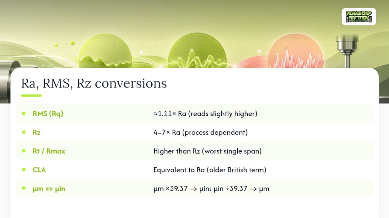
RMS runs about 1.11 times Ra, Rz typically lands 4 to 7 times Ra, and 39.37 converts micrometers to microinches. If a US print shows an unlabeled number under 500, it's almost always Ra in microinches. That's the whole conversion problem in one sentence, but the chart below is what you'll actually reach for at the bench.
Before you quote anything off this chart, check three things:
- Confirm the title block states units (µin vs µm) explicitly.
- Verify whether the functional parameter is Ra (average) or Rz (peak-to-valley) — they aren't interchangeable.
- Know that feed rate, not tooling budget, is usually your fastest lever on finish.
Pro Tip: If a print calls out a tight Ra with no Rz limit on a sealing surface, ask the designer whether Rz matters. Ra alone can hide a few deep valleys that ruin a seal even when the average looks fine.
Key Takeaways
Getting a surface finish chart right comes down to matching Ra, RMS, and Rz conversions to the process that can actually produce them, then verifying with a calibrated instrument.
| Point | Details |
|---|---|
| Core conversion math | RMS ≈ Ra × 1.11; Rz typically runs 4 to 7 times Ra depending on process. |
| Watch your units | Unlabeled US print values are usually Ra in microinches; use 39.37 to convert µm to µin. |
| Match finish to function | Don't default to the tightest Ra on the chart; every step down adds machine time. |
| Grinding is the floor changer | Ra below roughly 8 to 16 µin usually requires honing or grinding, not a lathe adjustment. |
| Flying Chip Factory quotes by function | The shop flags mismatched Ra/Rz callouts and over-specified finishes before quoting, with direct machinist access for fast answers. |
Surface Finish Chart: Full Ra, RMS, and Rz Conversion Table
Every surface finish chart worth using needs to show more than one parameter, because shops, designers, and inspectors don't always talk in the same units. Ra (arithmetic average roughness) is the workhorse in North American shops. RMS (root mean square, also called Rq) weighs deviations more heavily and tends to read slightly higher than Ra. Rz averages the peak-to-valley heights across several sampling lengths, while Rt (or Rmax) captures the single worst peak-to-valley span across the whole evaluation length. CLA (center line average) is the older British term for essentially the same measurement as Ra.
The table below extends the quick-reference chart with the multipliers engineers actually use to move between parameters.
The core math is straightforward: multiply Ra in micrometers by 39.37 to get microinches, or divide microinches by 39.37 to get micrometers. For RMS, multiply Ra by roughly 1.11. For Rz, the multiplier isn't fixed. It floats between 4 and 7 times Ra depending on the process and the peak shape, which is why industry references treat Rz as a range rather than a clean formula. Rt/Rmax runs even higher, since it captures the single deepest scratch or highest peak in the sample rather than an average. A full published conversion table is the fastest way to cross-check a value without doing the math by hand every time.
What Do 32, 63, and 125 Mean on a Print?
Shop shorthand collapses a lot of nuance into three numbers you'll see constantly: 32, 63, and 125. These aren't arbitrary. They map to what standard machining processes naturally produce without extra finishing steps.
- 125 µin (3.2 µm): General machining. Typical for as-milled or as-turned surfaces that aren't touching anything critical.
- 63 µin (1.6 µm): Fine machining. Common on mating faces, bolt patterns, and surfaces that need to look clean but don't seal against anything.
- 32 µin (0.8 µm): Very fine machining, often the practical floor for single-pass turning or milling before you need a secondary operation.
| Common Callout | Typical Application |
|---|---|
| 125 µin | Structural surfaces, non-mating faces |
| 63 µin | General mating surfaces, visible cosmetic faces |
| 32 µin | Bearing bores, precision fits, light sealing surfaces |
Pro Tip: Don't default to 32 µin because it "sounds safer" than 63. Every step down in Ra adds machine time and often a secondary operation. Match the callout to what the part actually needs to do, not to a habit carried over from the last drawing.
Which Machining Process Gets You the Ra You Need?
Every process has a realistic window, and pushing past it means adding a step rather than dialing in a parameter. Coarse turning or rough milling generally lands in the 250 to 500 µin range as-cut. General-purpose turning and milling settle into 125 to 250 µin without much extra effort. Fine machining, meaning tighter feeds, sharper inserts, and a bigger nose radius, gets you into 63 to 125 µin territory, and very fine single-point work can reach 32 to 63 µin.
The levers that move you inside these bands are feed rate, tool nose radius, insert geometry, and rigidity. Cutting feed in half roughly quarters the theoretical roughness on a single-point turning operation, which makes it the cheapest adjustment available before you touch tooling or add an operation.
- Bigger nose radius smooths the scallop pattern left between passes.
- Slower feed at consistent depth of cut improves finish more reliably than raising spindle speed alone.
- Rigid setups and sharp inserts matter as much as the programmed numbers.
Pro Tip: Turned and bored surfaces commonly bottom out around Ra 16 to 32 µin with feed and tooling tweaks alone. Anything tighter than roughly 8 to 16 µin usually means grinding or honing as a separate step, not a better lathe setting.
How Is Surface Finish Actually Measured?
A contact stylus profilometer drags a diamond tip across the surface and records vertical deflection, which is the standard for shop and lab measurement. Optical interferometers measure the same thing without touching the part, useful on soft or coated surfaces where a stylus could leave a mark.
- Sampling length (cut-off) sets the wavelength range the instrument evaluates. Too short a cut-off misses waviness; too long picks up form error that isn't really "roughness."
- Evaluation length is usually several sampling lengths averaged together, which is why a single scratch rarely tanks a whole Ra reading.
- Filters separate roughness from waviness and form, and picking the wrong filter changes your number without changing the surface.
Measurement uncertainty is real. NIST's calibration guidance notes that stylus tip radius, calibration drift, and sampling parameters all introduce variation, so two labs measuring the same part can report slightly different numbers even when both instruments are working correctly.
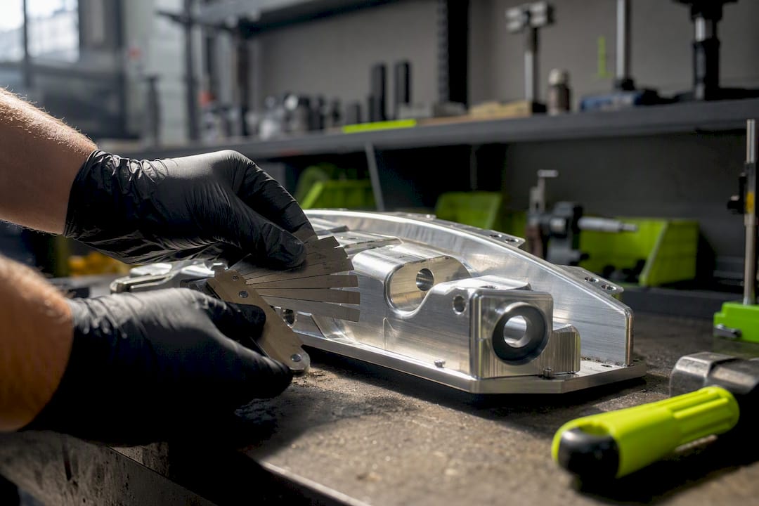
Pro Tip: Comparator plates with marked Ra values are fast for a shop floor go/no-go check, but they're a feel test, not a certified measurement. Reach for a calibrated profilometer for anything going into a spec sheet.
How Do You Specify Surface Finish on a Drawing?
The surface finish symbol, a checkmark shape, carries the Ra (or Rz) value directly above or beside it, positioned on the surface it applies to or on an extension line from that surface. Lay-direction symbols next to the checkmark indicate whether tool marks should run parallel, perpendicular, or crosshatched relative to a feature, which matters for sealing and wear surfaces more than cosmetic ones.
- Confirm the title block states the drawing standard, ASME Y14.36M or ISO 1302, since symbol conventions and default assumptions differ slightly between them.
- State units explicitly next to every finish callout. Never assume the reader will guess µin versus µm.
- Never list Ra and Rz values on the same feature that contradict each other. Shops will flag it and ask for clarification before quoting.
Roughly one in a handful of drawing revisions gets kicked back over ambiguous finish callouts alone, which costs a full quote cycle for something a clear title-block note would have prevented.
Pro Tip: If you're also specifying thread standards or anodize thickness on the same print, keep unit conventions consistent across every callout on the page, not just the finish symbol.
How Do You Convert Ra to RMS or Rz by Hand?
- Ra to RMS: Multiply Ra by 1.11. Example: Ra 63 µin × 1.11 ≈ 70 µin RMS.
- Ra to Rz: Multiply Ra by a factor between 4 and 7 depending on process. Example: Ra 63 µin × 4 to 7 ≈ 250 to 440 µin Rz.
- µm to µin: Multiply by 39.37. Example: 1.6 µm × 39.37 ≈ 63 µin.
The 39.37 conversion factor is where most unit errors happen. Misreading 1.6 µm as 1.6 µin understates the actual roughness by a factor of nearly 40, which is a serious mismatch if that number ends up driving an inspection decision.
Pro Tip: Sanity-check every conversion against the small reference table you keep at your desk. If your math lands outside the expected band for that process, you likely swapped µin and µm somewhere upstream.
What Do Machinists Wish Engineers Knew About Finish Callouts?
Specify finish by function, not habit. A structural bracket doesn't need the same Ra as a hydraulic bore, and asking for 32 µin across an entire part inflates cycle time for no functional gain.
- Use comparator plates for a quick shop-floor sanity check, but rely on calibrated profilometry for anything that ends up in a report.
- Flag any print where Ra and Rz values don't align before it goes out for quote, not after parts are cut.
- Reducing feed rate is usually the cheapest way to tighten finish before you reach for a finer insert or a secondary operation.
Pro Tip: Ask the machinist directly if a callout feels tighter than the part's job requires. A five-minute conversation before quoting saves a redo after first parts.
Half the finish disputes we see on a print aren't about the machine's capability. They're about a designer specifying 16 µin on a surface that never touches another part, then being surprised when the quote comes back higher than expected.
At Flying Chip Factory, that kind of conversation happens before the quote goes out, not after.
A Shop's Take on Reading a Finish Chart
A chart tells you what's achievable, not what's necessary. The real decision is whether a tighter Ra buys you function or just cost. When it's unclear, that's a five-minute conversation with a machinist, not a guess baked into the drawing. Flying Chip Factory's direct-access setup exists partly for this reason.
How Flying Chip Factory Handles Finish-Sensitive Parts
Flying Chip Factory quotes surface finish the way it should be quoted: based on what the surface actually does, not what looks safest on paper. As a CNC job shop built around prototype and short-run work, direct machinist access means a finish question gets answered in a call, not a support ticket queue three days later.

- Prototype and short-run CNC turning and milling with finish targets built into the quote.
- Grinding and honing coordination for Ra targets below what a single-pass lathe or mill can reach on its own.
- Direct contact with the machinist running your job, not an account manager relaying questions secondhand.
Most quotes get flagged for one of two things: mismatched Ra/Rz values on the same feature, or a finish spec tighter than the part's function requires. Catching that early keeps your turnaround honest. If you're specifying finish on a drawing with thread callouts or material temper notes that also affect achievable roughness, upload the print and Flying Chip Factory will flag anything that needs a second look before you get a number back.