
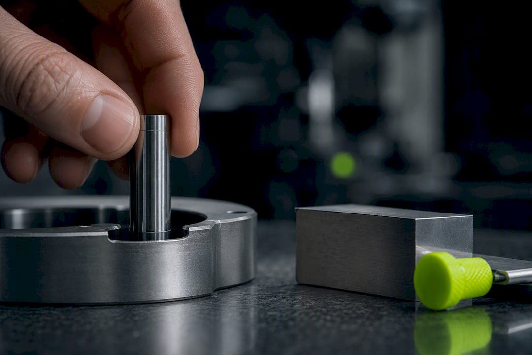
A slip fit is a clearance fit that lets one part slide into another by hand, with enough play to move freely but not so much that the parts wobble or rattle. Practical slip-fit clearances typically run from about 0.0005 inch to 0.005 inch (0.01 to 0.13 mm) depending on part size and application, and both dowel-pin tables and ASME Y14.5 tolerancing conventions anchor these numbers on real drawings.
TL;DR:
- Slip-fit clearances typically range from 0.0005 to 0.005 inch, but actual hole sizes depend on vendor specifications and manufacturing tolerances.
- Confirm actual manufacturer tolerances for dowel pins and shafts before finalizing hole sizes, as ground pins can be slightly oversized, affecting the fit.
- For repeated assembly and disassembly, looser fits are preferable, while tight fits suit single-location or fixed-position applications.
- Machining strategies such as reaming or boring, combined with careful measurement and verification with plug gauges, are essential to achieve precise slip-fit tolerances.
- Surface finish, coatings, and environmental factors like temperature significantly influence effective clearance and should be accounted for in the design and measurement process.
Quick-reference chart for slip-fit clearances
Dowel pins are the easiest place to see slip fit numbers in practice because pin makers publish exact hole sizes for both press and slip conditions. Engineers Edge's dowel pin table lists recommended press and slip fit hole diameters by pin size, toleranced per ASME Y14.5, and that table is the starting reference most shops pull from when a drawing calls for a dowel.
Read this table as a starting point, not a substitute for the pin maker's own sheet. Nominal diameter and actual manufactured diameter are rarely identical: WM Berg's dowel pin design guide notes that pins are commonly ground with a small positive tolerance above nominal, typically a few ten-thousandths of an inch, so a hole sized for "nominal" can end up tighter than intended. Always pull the vendor's spec sheet before committing a hole size to a drawing.
Metric equivalents follow the same logic. A 6 mm dowel typically pairs with a slip fit hole in the 6.01 to 6.03 mm range, and most drawing standards round metric clearances to two decimal places rather than trying to match imperial precision exactly.

How to choose the right slip fit for the job
Not every clearance hole needs the same tightness. A locating dowel that sets a fixture's position once and stays put wants the snug end of the slip range. A sliding shaft in a linear bearing, or an alignment pin that gets pulled and reinserted during assembly, wants a looser fit so it does not gall or bind after repeated cycles.
Before you commit a number to the drawing, check:
- Assembly frequency: parts that mate once can run tighter than parts assembled and disassembled repeatedly.
- Finish and lubrication: a lubricated bore tolerates a tighter clearance than a dry one without binding.
- Thermal range: if the assembly sees a wide temperature swing, budget extra clearance so thermal growth does not turn a slip fit into an interference fit.
- Plating or coating: anodizing, black oxide, or plating adds thickness that eats into your clearance before the part ever gets assembled.
- Vendor pin or shaft tolerance: confirm actual OD against the spec sheet, not the nominal callout.
As a rule of thumb, a clearance under a very small threshold on a steel shaft is close enough to cross into a transition or interference fit, according to practitioner discussion on the topic, so treat that range as a warning line rather than a target.
Pro Tip: Request the supplier's pin or shaft spec sheet before finalizing a hole size, and call out both a maximum and minimum bore diameter on the drawing instead of a single nominal number.
Manufacturing methods that hold slip-fit tolerances
Getting a bore to land inside a few thousandths of an inch is a process choice as much as a design choice. Most shops follow a sequence like this:
- Drill or bore near size to leave consistent stock for the finishing operation, avoiding a finish pass that has to remove uneven material.
- Ream to final diameter for holes under roughly 1 inch, since a reamer produces a straighter, rounder bore than drilling alone and repeats well across a production run.
- Bore for larger diameters where reamers become impractical, taking a light single-point finish pass to control size and surface finish together.
- Verify with a plug gauge or bore mic before releasing the part, rather than trusting the machine's last recorded position.
Reamer selection matters as much as the reaming step itself: shops commonly run a reamer sized slightly under the final target and take a light finish pass to true up the bore, since an oversize reamer cannot be corrected without starting over. Inspection should include a go/no-go plug gauge for a fast pass/fail check, a bore mic or CMM for a shaft, and attention to roundness rather than diameter alone, since an oval bore can pass a diameter check but still bind a pin.
Common pitfalls include heat build-up during reaming that causes the bore to shrink slightly after cooling, loose fixturing that lets the part walk mid-cut, and forgetting to account for coating thickness before the part goes out for plating. A shop's own reaming versus boring practice usually settles these tradeoffs based on hole size and quantity rather than a single fixed rule.
Material, finish, and temperature effects on clearance
The nominal clearance on a drawing is not the clearance the assembly actually experiences once material and environment enter the picture. Steel and aluminum expand at different rates, so a steel pin in an aluminum housing that sees a wide temperature swing can tighten or loosen depending on which part grows faster, and that difference matters more as bore size increases.
Surface finish changes how much clearance you actually need. A smoother bore, in the range shops typically target for sliding fits, lets a pin move with less resistance than a rougher one at the same nominal clearance, and adding lubrication further reduces the effective drag, sometimes allowing a slightly tighter design clearance than a dry fit would tolerate.
Coatings and platings add thickness that has to be subtracted from the pre-coating clearance. Black oxide adds very little, while heavier platings can measurably tighten a fit that was slip when bare. Call out material, finish, and any coating directly on the drawing, and request the supplier's process spec sheet rather than assuming a standard thickness.
How Flying Chip Factory specs and machines slip fits
The decision flow for choosing machining methods starts with the nominal size, then a check against the dowel or shaft vendor's actual tolerance sheet before any metal gets cut. From there reaming is chosen for smaller bores or boring with a finish pass for larger ones, and every slip-fit hole gets a plug gauge or bore mic check before the part ships.

A typical drawing note might read "hole diameter 0.2510 to 0.2515 in, ream to size, verify with class Z plug gauge." That level of specificity avoids the ambiguity that turns a slip fit into an accidental press fit on the shop floor.
For more detail on the numbers behind dowel-pin holes, see our dowel pin hole tolerance reference, and for the reaming and boring tradeoffs that drive our process choice, see our reaming versus boring guide.
What the numbers actually tell you about slip fit
The conventional advice treats slip fit as a lookup problem: find the chart, pick the row, done. That undersells the risk. The real failure point in most shops is not picking the wrong clearance number, it is assuming the vendor's nominal pin or shaft size matches the part actually sitting on the bench. A pin ground 0.0002 inch over nominal, paired with a hole reamed to nominal, produces a press fit nobody intended.
If you take one thing from this guide, take this: spend less time debating whether 0.0008 inch or 0.0012 inch is the "correct" clearance, and more time confirming the actual measured size of the mating part before you finalize the bore. Coating thickness, finish, and thermal exposure move the real-world fit far more than the difference between two reasonable clearance choices on paper. Measurement discipline beats chart precision every time.
— Drake
Request prototype or short-run machining from Flying Chip Factory
If you have a drawing with a slip-fit callout and need it cut right the first time, that type of job is common in precision CNC machining shops. Such shops may machine and ship in-house from a single location, with the same person designing, cutting, and answering questions, so a clearance that needs adjusting after a first-fit check can get corrected efficiently.

Services typically handled for engineers and small manufacturers include:
- Prototype machining for parts that need a first-fit check before a production run.
- Short-run production for orders too small for a big shop's minimums.
- Fixtures, brackets, and support parts built to specified tolerance callouts, including slip and press fit bores.
You can see our own precision work on the E2 Kickstand for KTM SX-E 2, GASGAS MC-E 2 and Husqvarna EE 2, or send us your drawing directly through Flyingchipfactory to get a quote.
Standards and guides worth keeping on hand
For drawing standards and dowel-pin sizing, keep these on your reference shelf:
- Engineers Edge dowel pin table, for recommended press and slip fit hole diameters by pin size, toleranced per ASME Y14.5.
- WM Berg's dowel pin design guide, for choosing pin OD by fit type and understanding manufactured pin tolerances.
- Engineering Stack Exchange discussion on hole-to-shaft tolerance, for practitioner-level detail on how small tolerance shifts change fit class.
- Mosaic Safety's guide to precision engineering facility practices, for shop process controls relevant to consistent tolerance work.
- Tight tolerance machining guide, for measurement methods and process notes on holding tight bores.
Use the first two for drawing notes, and the Stack Exchange thread and tight tolerance guide when you are troubleshooting a fit that came back tighter or looser than expected.
Sources
FAQ
What is the tolerance range for a sliding fit?
Sliding, or slip, fits typically run from about 0.0005 to 0.005 inch (0.01 to 0.13 mm) of clearance depending on part size, based on dowel pin tolerance tables. Smaller pins and shafts sit toward the tighter end, and larger diameters or looser-running applications sit toward the wider end.
Is 0.005 a tight tolerance?
A clearance of 0.005 inch sits at the loose end of the typical slip fit range rather than the tight end. For most dowel pin and shaft applications, a tolerance that tight in the "close" sense would be toward the tighter end of the slip fit range, per dowel pin sizing references.
What is the tolerance for a slip fit dowel pin?
Slip fit dowel pin holes are typically sized 0.0005 to 0.0010 inch larger than the pin's nominal diameter, according to manufacturer dowel pin tables. Always check the pin vendor's own spec sheet first, since pins are often ground slightly over nominal, which can tighten the actual fit.
How much tolerance is needed for a friction fit?
A friction, or interference, fit generally requires the shaft to be sized larger than the hole rather than smaller, reversing the clearance relationship used for slip fits. Practitioner discussion on hole-to-shaft sizing notes that a shift of just 0.0002 to 0.0003 inch can move a bore from a slip condition into an interference condition, so precise measurement matters more than a fixed target number, per engineering practitioner guidance.