
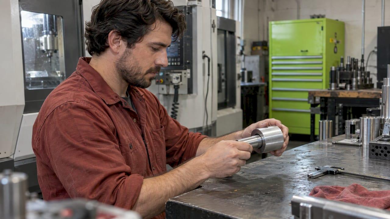
Slip fit clearance is the guaranteed gap between a hole and the shaft, pin or part that goes into it, sized so the two go together by hand and come apart the same way. How big that gap should be depends on the job: a locating feature wants a gap of a few ten-thousandths of an inch to a few thousandths, and a free-sliding part wants more. The way to get it right is to work out the minimum and maximum clearance from both tolerances, then check that the coating, material and temperature do not eat the gap. This guide shows how, with a worked example.
We machine motorcycle parts and customer prototypes in one shop in Athens, Alabama, so this is the arithmetic we run before a print goes on a machine.
TL;DR
- Slip fit clearance = hole diameter minus shaft diameter. Worst-case minimum is the smallest hole minus the largest shaft; worst-case maximum is the largest hole minus the smallest shaft.
- A true slip fit keeps the minimum clearance above zero, so parts assemble by hand at the tolerance extremes.
- Fit tables list diametral clearance (the whole gap). Radial clearance, the gap per side, is half of it. Check which one your drawing means.
- Coatings, hardcoat anodizing especially, and mixed-material heat growth can use up the gap. Put them in the tolerance stack before you release the print.
- Fit examples change with diameter. Never copy an H7/g6 number from one size to another.
What slip fit means
A slip fit is a clearance fit: the limits of the mating parts are chosen so there is always clearance at assembly. The Government of Canada's terminology database defines a clearance fit that way and records "sliding fit" as an accepted term for it. On shop floors, "slip fit" usually means the snug end of that family: the part drops in, locates well and has no perceptible slop.
Three terms are worth fixing in your head before any numbers:
- Clearance fit: the hole is always larger than the shaft, even when both are at their worst-case sizes.
- Transition fit: depending on where the actual sizes land, the pair may have a little clearance or a little interference.
- Interference (press) fit: the shaft is larger than the hole, so the pair must be pressed together.
If a drawing says "slip fit" and nothing else, the machinist has to guess the number. That is the main reason this topic exists: the phrase describes a feel, and a part needs a figure.
How to calculate slip fit clearance
The math is subtraction, done at the extremes of each tolerance. Tolerance limits are applied algebraically to the basic size, and the resulting differences are the minimum and maximum clearance, as the ANSI B4.1 fit tables describe.
- Minimum clearance = smallest hole minus largest shaft.
- Maximum clearance = largest hole minus smallest shaft.
If the minimum is positive, every part that passes inspection will assemble. If it is zero or negative, some pairs will bind.
A worked example
Take a 12 mm locating pin in a bracket. Illustrative limits:
| Feature | Smallest | Largest |
|---|---|---|
| Hole | 12.000 mm | 12.018 mm |
| Shaft | 11.984 mm | 11.995 mm |
- Minimum clearance: 12.000 − 11.995 = 0.005 mm
- Maximum clearance: 12.018 − 11.984 = 0.034 mm
That is 0.005 to 0.034 mm of diametral clearance. The gap on each side, the radial clearance, is 0.0025 to 0.017 mm. The pin always goes in, and at worst it rattles by about thirty-four thousandths of a millimeter across the diameter.
A published example from the University of Darmstadt's engineering tutorial runs the same way. A 7 mm H7/f7 fit has hole limits of 7.000 to 7.015 mm and shaft limits of 6.972 to 6.987 mm, which gives 0.013 to 0.043 mm of clearance. Read the clearance from the listed limits themselves.

Diametral or radial?
This is the mistake that costs the most. A 20.02 mm hole on a 20.00 mm shaft is 0.02 mm of diametral clearance but only 0.01 mm per side. Fit tables list diametral clearance. If a designer reads "0.01" off a sketch and the shop reads it as the whole gap, the part is off by a factor of two. Write "diametral" on the print when it matters.

Reading ISO and ANSI fit codes
Two systems cover most prints.
ISO 286 (metric). A code such as H7/g6 has a hole half and a shaft half. The capital letter marks a hole, the lowercase letter marks a shaft, and the number is the tolerance grade: a smaller number is a tighter band. H is a hole whose lower limit sits at basic size, so the hole can only be larger. Because the shaft letter g sits just under basic size, H7/g6 always leaves a small positive gap.
ANSI B4.1 (inch, US). Running and sliding fits are labeled RC1 through RC9, and locational clearance fits are labeled LC. The ANSI tables are the ones most US print reviewers expect to see in inch drawings.
How the common choices behave in practice, going by the descriptions in the IIT Kanpur fits reference:
| Fit | What it does | Typical use |
|---|---|---|
| H7/g6 | Very small clearance, accurate guidance | Sliding gears, clutch disks, pistons, rods sliding in bearings |
| H8/h9 to H7/h6 | Small clearance for precise guidance and centering; assembled by sliding without great force | Locating and centering parts |
| H7/f7 and looser | More clearance for running or free movement | Parts that turn or slide with lubrication and some heat |
The same reference notes that, once lubricated, parts in the small-clearance group can be turned and slid by hand. That is the feel most people mean by "slip fit."
Why the same code gives different gaps at different sizes
ISO tolerance bands grow with nominal diameter. An H7/g6 fit on a 12 mm part and on a 60 mm part do not have the same clearance in microns. Copy a number from a 25 mm example into a 60 mm design and the gap is wrong. Always look up the band for your basic size, or give the machinist the min and max you want directly.
Free sliding or precise location?
The fit you pick depends on whether the part has to move or has to stay put and be accurate.
The Darmstadt tutorial frames fit selection by function: first decide whether the joint should be snug or loose enough for relative movement, then choose from the table. A practical way to apply it:
- The part is removed often and must land in the same place every time (a fixture locator, a bracket on dowels). Choose the tight end of the clearance range. A minimum clearance of a few ten-thousandths of an inch to a thousandth keeps location repeatable.
- The part slides or rotates under light load. Choose H7/g6 or a similar sliding fit with a small but positive minimum.
- The part must never bind, even when dirty, hot or coated. Open the clearance. A looser fit is a cheaper and more reliable answer than a tight fit that needs hand lapping.
We go deeper on the inch ranges in our guide to slip fit tolerances, and on locating pins in our dowel pin hole tolerance reference.
Dowel pins are a special case
A hardened dowel pin is not exactly basic size. It is ground slightly oversize, so a hole reamed to nominal can be a press fit, not a slip fit. If you want a slip fit, the hole has to be opened up a little beyond the pin's actual size. Two pins are the usual limit for alignment, because a third over-constrains the part: every extra pin fights the others over a few tenths of a thousandth of position error. Give the two-pin pattern as much room as the job allows.
What eats your clearance after machining
The print is a theory. These are the places a good clearance disappears.
Coatings and anodizing
A coating adds material to the surface, and it adds it to both sides of a gap. Anodizing grows partly into the metal and partly out of it, and hardcoat is thick enough to matter on a close slip fit. If the part is anodized after machining, the hole shrinks and the shaft grows. The fix is to dimension the finished size, or to machine to a pre-coat size that includes the build-up. Our hardcoat anodize thickness guide covers how to specify it so the shop and the finisher agree.
Heat and mixed materials
Aluminum grows faster than steel when it warms. A steel pin in an aluminum bore can open up in a hot assembly and tighten when cold, so a fit that works at room temperature may be wrong at operating temperature. The ANSI sliding-fit descriptions carry a related warning: the tightest sliding fits in larger sizes may seize with small temperature changes. If your part sees heat, such as an engine area or a brake, calculate at the working temperature.
Geometry, not just size
A hole can be the right diameter on average and still be out of round, tapered or bowed. A pin that measures 11.990 mm at one point and 11.996 mm at another does not fit like a perfect cylinder. On tight slip fits, call out roundness, cylindricity or straightness as well as size, and keep the surface finish smooth on the mating faces. Our tight tolerance machining guide lists which of these controls pay for themselves.
Stack-up
If two slip-fit features sit on the same part, as with two dowel holes, the position tolerance of each hole adds to the size clearance. This is why a pair of pins needs more room than a single one. Add the position errors to the picture before you declare victory on size.
Putting a slip fit on the print
A print that gets the right part the first time does five things:
- States the fit with the limits, not just the code. For example, "hole Ø12.000/12.018, pin Ø11.984/11.995".
- Says whether clearance is diametral.
- Says whether dimensions are before or after coating.
- Gives the material, so the shop can think about thermal growth and tool deflection.
- Calls out the critical geometry and finish on the mating surfaces.
Our CNC drawing standards guide shows how to lay this out so nothing is left to interpretation, and our DFM guide covers designing features that cut well in the first place. Both save revision rounds.
How we work with slip fits
A slip fit is a conversation between the person who drew it and the person who cuts it. In our shop that is the same machinist. When a customer sends a pair of parts with a tight fit, the question "what does this need to do?" gets answered directly, before the program is written, and a tolerance can be adjusted while the part is still on the drawing board. Our own parts are designed and machined in one place for the same reason: fit, durability and installation are decided by the person who builds them.
That shows in the parts we sell. The E2 Kickstand is CNC-machined for the KTM SX-E 2, GASGAS MC-E 2 and Husqvarna EE 2 electric mini bikes and bolts on, so the fit work is done before it reaches your garage.
Our view: the number belongs on the print
We have a simple rule: if a fit matters, it gets a number. "Slip fit" is a good shorthand and a poor specification. When we design our own motorcycle parts, we decide what each mating surface has to do, pick the clearance for that job, and machine to it, because a kickstand or a handlebar mount that rattles or binds is a part a rider notices every ride.
We would rather talk to a customer about the limits than guess at them. Sending the hole and shaft limits, the material and the finish lets us tell you quickly whether a fit is easy, tight or worth loosening a few thousandths for a cheaper, more reliable part.
The shop that machines the part should be the one that can answer how it will fit. That is why we keep design, machining and shipping under one roof.
Drake
Need the parts machined?
If you have a print with a slip fit, a fixture that needs to locate repeatably, or a bracket that has to match a mating part, we handle prototype machining, short-run production and fixtures, brackets and support parts. You talk to the machinist directly, so questions about clearance get answered while the design can still change.

If you ride a KTM SX-E 2, GASGAS MC-E 2 or Husqvarna EE 2, our E2 Kickstand is a CNC-machined, bolt-on replacement for the factory triangle stand, priced at $100–$105.
FAQ
How much clearance do you need for a slip fit?
There is no single number, because it depends on diameter and function. As a rule, the minimum clearance should be above zero so parts assemble by hand at worst-case sizes. Locating features typically need only a few ten-thousandths to a few thousandths of an inch, and free-sliding parts need more. Calculate it from your own hole and shaft limits.
What is the difference between a slip fit and a clearance fit?
A slip fit is a kind of clearance fit. Clearance fit is the broad category: the hole is always larger than the shaft. "Slip fit" or "sliding fit" usually refers to the snug end, where the clearance is small enough for accurate location but large enough to assemble by hand.
What does H7/g6 mean?
It is an ISO 286 fit code. H7 describes the hole, g6 describes the shaft, and the numbers are tolerance grades. The pairing always leaves a small positive gap, so it is a sliding fit with accurate guidance. The actual gap changes with the nominal diameter, so look it up for your size.
Does anodizing change a slip fit?
Yes. Anodizing adds thickness, and hardcoat adds the most. A hole that measures right before coating can be too tight after, and a shaft can grow into the gap. Specify whether your dimensions apply before or after finishing, and allow for the build-up in your clearance.
Sources
- TERMIUM Plus: clearance fit entry, Government of Canada
- ANSI B4.1 fit tables (Dimensioning, Gaging, and Measuring)
- Selection and calculation of fits, University of Darmstadt
- Clearances and Fits: Guidelines and Tables, IIT Kanpur