
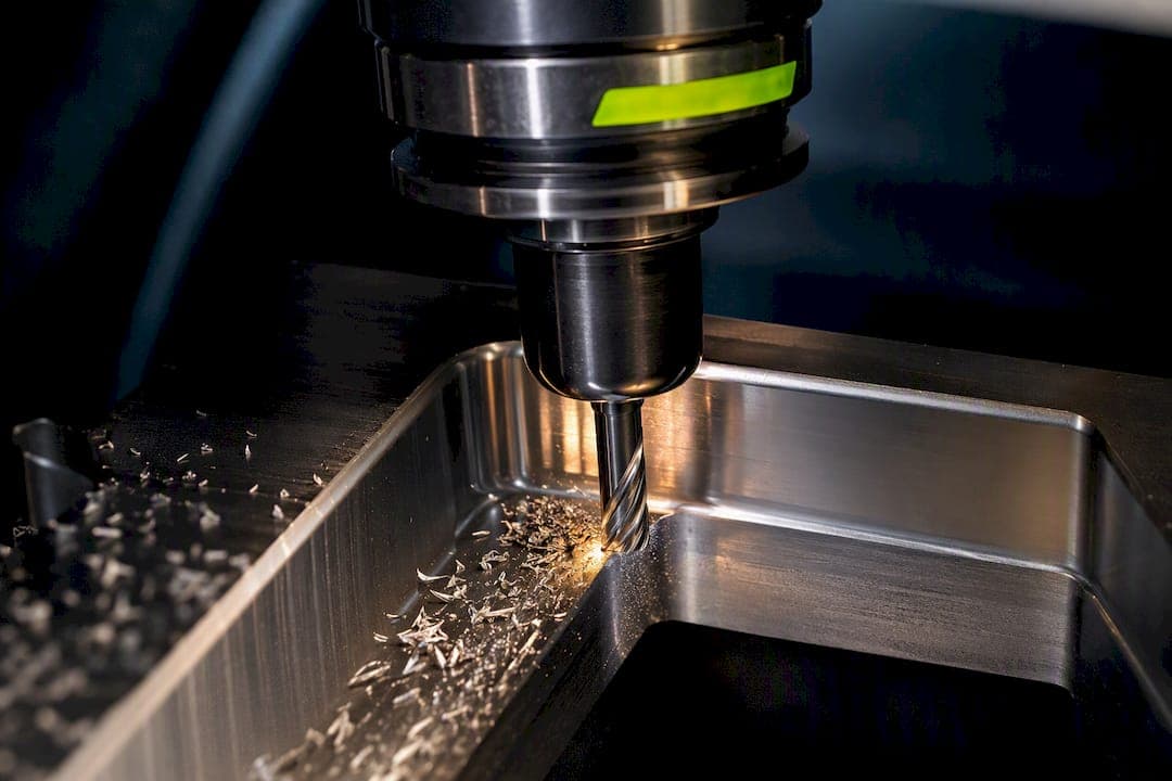
An inside corner radius is the curved fillet where two internal surfaces meet, and the rule that governs it never changes: a rotary cutter can't cut a radius smaller than its own finishing diameter allows for stable engagement. If your drawing calls for a tighter radius than your tool can produce, you either size up the radius, switch cutters, or plan a secondary process like EDM. Everything else below is about getting the numbers and the process right.
TL;DR:
- Inside corner radii cannot be smaller than the finishing diameter of the cutter used, requiring larger tools or secondary processes for tight curves.
- Key formulas such as tangent offset, arc length, and sagitta are essential for calculating and inspecting inside corner radii accurately.
- Methods like using radius gauges, fitting circular objects, or CMM measurements should match the required tolerance, with repeatability emphasized over single readings.
- For radii smaller than what the cutter can produce, options include switching to smaller tools, using EDM, or adjusting design tolerances for manufacturability.
- Clear radius callouts with explicit size, tolerance, material, and inspection method on drawings prevent guessing and costly redesigns.
What Is an Inside Corner Radius, and What Formulas Define It?
An inside corner radius (R) is the arc that replaces a sharp interior vertex where two walls meet. Machinists also call it an internal fillet or an inside corner profile, and it shows up on nearly every pocketed or ribbed part that comes off a CNC mill. The angle between the two intersecting surfaces, θ, determines how the arc sits relative to the corner, and converting θ to radians is the first step in any hand calculation.
Three formulas do most of the work. The tangent offset tells you how far back from the theoretical sharp corner the arc actually begins: T = R / tan(θ/2). Arc length (L = R × swept angle in radians) tells a CAM programmer how much material the tool travels through on that curve. Sagitta, S = R × (1 − cos(swept angle/2)), tells an inspector how far the arc bows in from a straight chord, which matters when you're checking a radius against a flat reference edge.
| Term | Formula | Used by |
|---|---|---|
| Tangent offset (T) | R / tan(θ/2) | CAM programmers, tangent point layout |
| Arc length (L) | R × swept angle (radians) | CAM toolpath and cycle time estimates |
| Sagitta (S) | R × (1 − cos(swept angle/2)) | Inspectors checking radius against a chord |
Keep those three in your back pocket. You'll use tangent offset constantly when programming toolpaths, and sagitta comes up more often than you'd expect during inspection.
How Do You Measure an Inside Corner Radius?
The method you pick should match your tolerance band, not just what's sitting on the bench. A quick check on a bracket that's going into a jig doesn't need the same rigor as a mating surface on a flight part.
- Ruler and square method: draw or project tangent lines from both straight edges into the corner; where they intersect approximates the radius center. Fast, but accuracy suffers past ±0.010 inch.
- Circular object fitting: press a drill bit, dowel, or ball bearing into the corner until it seats flush against both walls. If it fits perfectly, the corner radius equals half the object's diameter. Cheap and surprisingly reliable for a shop-floor gut check.
- Radius gauge sets: a fanned set of leaf gauges, each ground to a known radius, gets slid into the corner until one seats with no light gap. This is the standard mid-accuracy method most shops keep in a drawer.
- 3D-printed slivers and custom templates: printed to an exact radius, these give a repeatable check that beats a ruler on accuracy and cost almost nothing to produce in a range of sizes.
- CMM and optical comparator: for tight-tolerance work, a coordinate measuring machine or optical comparator captures the arc digitally and outputs a dimensional report. This is where you go when a drawing calls for ±0.002 inch or tighter.
Whichever method you choose, check twice. Burrs from machining or deburring can throw off a gauge reading, and tool overhang near deep corners sometimes leaves a slightly larger radius than programmed. Repeatability matters more than any single reading.
What Limits How Small an Inside Corner Radius Can Be?
Inside corners are unstable to machine because the cutter's arc of engagement spikes the moment it enters the corner. On a straight wall, a cutter might only be engaged across a small arc of its circumference. Drop it into a tight inside corner and that engagement arc balloons, which means more of the flute is cutting at once, forces climb, and chatter or tool deflection follows.
Sandvik Coromant's machining guidance puts a number on it: keep the programmed radial engagement around half the cutter diameter for stable roughing, and for accurate finishing, the finishing cutter's diameter should be no more than 1.5 times the component's corner radius.
A rule worth memorizing: if your part calls for a small inside radius, your finishing cutter needs a diameter no larger than roughly 0.1875 inch. Go bigger than that and you either can't reach the radius cleanly or you leave excess stock in the corner.
- If the drawing radius is smaller than any practical finishing cutter, your options are explained in detail in this explanation of glass machining for engineers: switch to a smaller diameter tool, open up the radius slightly if the design allows it, add an EDM operation to cut the sharp corner electrically, or plan a manual blending pass.
- On the CAM side, limit radial engagement with trochoidal or circular interpolation moves rather than a straight plunge into the corner, and separate roughing from finishing so the finishing pass removes a light, consistent shell rather than fighting leftover stock.
- Where the design tolerates it, program a slightly larger radius than the print's minimum. That extra margin often lets you run a bigger, more rigid roughing cutter, which speeds up cycle time without touching the finished geometry that matters.
Pro Tip: If a part has several inside corners at different radii, program the tightest one first while the cutter is fresh and sharp. Radius accuracy degrades faster on a worn tool, and you don't want your smallest, most visible fillet to be the one machined last on a dulling edge.
What Should You Put on the Drawing to Avoid Machining Headaches?
A radius callout without context forces the shop to guess, and guessing costs you money and lead time. Give the machinist enough information to quote accurately the first time.
- State the radius and its tolerance explicitly, and note whether EDM or hand finishing is acceptable if the milled radius can't hit the callout. A bare "R.125" with no tolerance band leaves too much open to interpretation.
- Size the radius with real cutters in mind. A 0.250-inch radius is trivial to hit with common finishing tools; a 0.031-inch radius on a deep pocket may force a specialty micro-end mill and a slower feed rate, which shows up in your quote.
- Specify material, surface finish, and inspection method. Whether the corner needs a CMM report or a quick gauge check changes both cost and turnaround.
- Talk to the machinist before finalizing tight radii. A five-minute conversation during design review routinely saves a redesign cycle after the first article comes back out of tolerance.
Pro Tip: If you're not sure what radius is realistic for a given pocket depth, ask for a design-for-manufacturability review before you release the drawing. Reading through our own notes on machining motorcycle parts shows how much a five-minute conversation with the shop up front changes the final tool list.
A Step-by-Step Workflow for Measuring and Specifying a Radius
Here's the sequence we'd follow on a bench, whether you're reverse-engineering an existing part or checking a first article against a print.
- Measure the existing corner with the method suited to your tolerance, whether that's a gauge set, a fitted dowel, or a CMM scan, and take at least two readings to confirm repeatability.
- Compare the measured or required radius against available finishing cutters. If the numbers don't line up, decide now whether you're opening the radius, swapping tools, or adding a secondary process like EDM.
- Program the toolpath with engagement limits in mind. Keep radial engagement near the 50% DC guideline for roughing, run a dedicated finishing pass, and confirm the finishing cutter diameter falls within the 1.5x rule for the corner radius.
- Inspect the finished part with a go/no-go gauge for quick jobs or a CMM report for tight-tolerance parts, and document the acceptance criteria so the next run doesn't reopen the same debate. Our guide on tight tolerance machining covers how to structure that inspection report so it holds up on repeat orders.
Skip step two and you'll find out the hard way, mid-cycle, that your tool list doesn't match your print.
What We've Learned Machining Inside Corners at Flying Chip Factory
Every prototype that lands on our floor in Athens, Alabama, has at least one corner that looked fine on screen and turned into a conversation once we started programming it. That's normal. The print says one radius, the tool crib has another, and somebody has to decide which one bends.
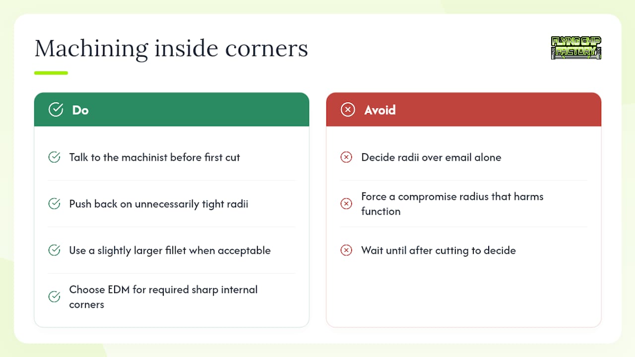
We tend to push back gently when a radius is tighter than it needs to be. A slightly larger fillet often lets us run a bigger, more rigid finishing cutter, which shortens cycle time on a short-run job without changing how the part functions. Other times the geometry genuinely needs a sharp internal corner, and EDM is the honest answer rather than forcing a compromise radius that doesn't do the part any favors.
None of this works well over email alone. The fastest fix is almost always a direct conversation with whoever is running the machine before the first cut, not after.
— Drake
Get Your Inside Corner Radii Machined Right the First Time
Guessing at tool sizes after the drawing is already released costs you a redesign cycle you didn't budget for. Flying Chip Factory works differently: you talk directly with the machinist running your job, not a sales layer between you and the spindle, so radius questions get answered before they turn into a rejected first article.

We handle CNC prototyping, short-run production, and fixture or replacement part fabrication, and inside corner geometry is one of the first things we flag during a design-for-manufacturability review. If your radius is tighter than a standard finishing cutter can reach, we'll tell you whether a smaller tool, a slightly larger fillet, or an EDM pass makes more sense for your budget and timeline, the same tradeoffs discussed in our rapid CNC prototyping process. Send us your drawing and get a straight answer on what your inside corners will cost to machine at Flyingchipfactory.
Sources
- Milling inside corners
- How To Measure a Corner Radius | Technical Guide
- Easy Guide on How to Measure a Corner Radius Accurately - MeasuringKnowHow
FAQ
How Do You Find the Radius of an Inside Corner?
Fit a circular object like a drill bit or ball bearing into the corner until it seats flush against both walls; the radius equals half that object's diameter. For tighter tolerances, use a radius gauge set or a CMM scan instead.
What Does Corner Radius Mean?
Corner radius refers to the size of the curved arc, measured in R, that replaces a sharp vertex where two surfaces meet, whether that corner is internal (inside) or external (outside).
How Do You Calculate the Inner Radius?
Use the tangent offset formula, T = R / tan(θ/2), along with the corner angle to locate tangent points, or measure directly with a gauge, template, or CMM and back-calculate using the sagitta formula if you only have a chord measurement.
What Is a Standard Inside Bend Radius for Steel?
There's no single universal standard since it depends on the sheet thickness, alloy, and grain direction, but the practical minimum for milled internal corners always comes back to the finishing cutter's diameter rather than a fixed steel spec.
Can a Machine Shop Produce a Sharp Inside Corner With No Radius?
Not with a standard rotary cutter, since the tool's own diameter sets a physical minimum. A truly sharp inside corner requires a secondary process like EDM or hand finishing, which some machine shops can quote alongside the milled features.