
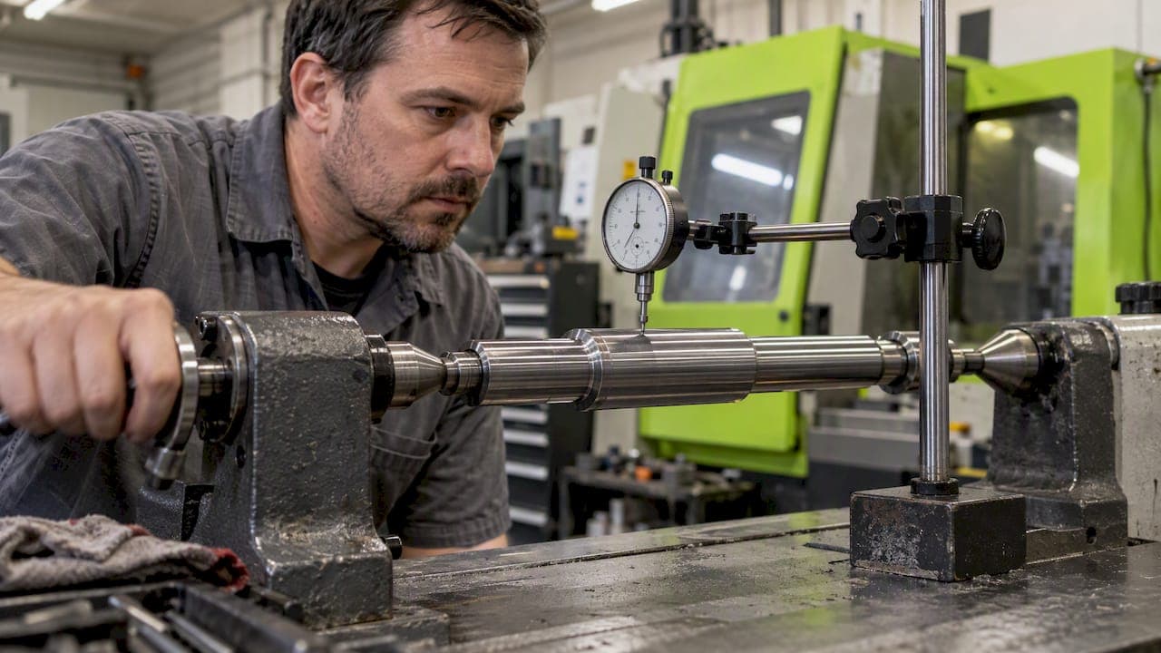
Concentricity and runout both deal with how well a round feature lines up with an axis, but they control different things. Concentricity controls an invisible set of derived midpoints. Runout controls what the surface actually does as the part spins. For most rotating parts, runout is the callout you want: it is easier to inspect, it is unambiguous, and it catches the errors that cause vibration. This guide explains the difference, the circular versus total runout question, and how to choose.
TL;DR
- Concentricity controls the derived median points of a feature against a datum axis. It is abstract and slow to verify. It was removed from the ASME Y14.5-2018 standard.
- Runout controls surface behavior as the part rotates about a datum axis. Circular runout checks each cross-section on its own. Total runout checks the whole surface at once.
- A part can be concentric and still have poor runout, because lobing or ovality shows up in an indicator reading but not in median points.
- For new US drawings, use position for axis location or runout for rotating surfaces. On ISO drawings, concentricity (coaxiality) is still valid, so check which standard governs.
- Call out circular runout unless taper, bow or barrel shape would hurt function. Total runout costs more to inspect.
What concentricity actually controls
Concentricity is a three-dimensional tolerance. Picture a cylinder. At every cross-section, take pairs of diametrically opposite points on the surface and find the midpoint of each pair. Those midpoints form a line, the derived median line. Concentricity requires every one of those midpoints to sit inside a cylindrical tolerance zone centered on the datum axis.
That definition is why the control is awkward. You cannot touch a derived median point. Nothing on the part marks it, and a dial indicator cannot read it. Geometric Learning Systems notes that circular runout controls circularity and concentricity together in a single reading, which is exactly why shops reach for runout as a stand-in.
The key consequence: concentricity ignores the shape of the surface. A bore that is slightly oval can be perfectly concentric, because opposite points still average to the center. As Cross Company's metrology primer explains, concentricity and runout measure different geometric characteristics, so there is no direct conversion between a runout number and a concentricity number.
What runout controls
Runout is a surface control. You mount the part on its datum axis, rotate it, and watch the full indicator movement. Whatever the surface does while turning counts: an offset axis, an out-of-round section, a lobed shape. All of it moves the needle.
That makes runout a composite check. It captures concentricity error and circularity error in one reading. For rotating parts, this is usually the thing you care about anyway. A shaft that wobbles in a bearing does not care whether the wobble came from an offset center or an oval cross-section.
Two details matter:
- The datum axis must come from a different feature than the one you are controlling, typically a bearing journal pair or a bore. A feature cannot be its own reference. If you need to review how datums are chosen, our guide on GD&T datums and assembly failures covers the three checks we run before cutting.
- The reading is full indicator movement, often called TIR in shop talk. Modern Machine Shop has a useful column on using TIR versus concentricity to control coaxiality, and it makes the same point: runout uses surfaces to control an axis.
Circular runout vs total runout
This is the second half of the search, and the confusion is common.
Circular runout is a two-dimensional control. It applies at any single cross-section as the part rotates, and each section is judged independently. Think of a ring of measuring points at one station along the length.
Total runout is a three-dimensional control. The indicator travels along the whole surface while the part rotates, and the combined reading must stay inside the tolerance. That is why total runout also controls taper, barrel shape and bow along the length, errors that circular runout can miss. GD&T Basics draws the same line: circular runout is a per-section check, total runout covers the entire surface.
| Control | Dimension | What it checks | Catches taper or bow? | Inspection effort |
|---|---|---|---|---|
| Concentricity | 3D | Derived median points vs datum axis | No, it ignores surface form | High, usually needs a CMM |
| Circular runout | 2D | Each cross-section separately | Not along the length | Low, a dial indicator on a rotating setup |
| Total runout | 3D | Entire surface at once | Yes | Moderate to high, more traverse and more reading |
The tolerance zones also differ in practice. Concentricity gives you a cylindrical zone for the median points. Runout gives you a limit on indicator movement. Because the indicator reads the full surface variation, a runout value already includes the doubling effect of an offset axis: a part whose axis is off by 0.001 inch shows 0.002 inch of indicator movement. That is one reason people ask whether concentricity is half the runout. It is a rule of thumb for a perfectly round part, not a conversion. GD&T Basics covers that question directly. Once the surface is not round, the shortcut breaks.
Why ASME dropped concentricity and ISO kept it
The ASME Y14.5-2018 standard removed concentricity and symmetry. The NIST guide on GD&T for digital manufacturing includes a clarification on exactly why and how to replace them. The short version: the definition based on median points was easy to misread and costly to verify, so the standard points users to position for axis control, or runout when the real concern is surface behavior.
Do not conclude concentricity is dead everywhere. Under ISO 1101, coaxiality and concentricity controls remain valid. If you receive a drawing from an overseas supplier, a legacy print, or a customer working to ISO, check the governing standard in the title block before you decide that a concentricity callout is a mistake. Treating it as obsolete on an ISO print can mean machining to the wrong requirement.
When you inherit a concentricity callout on an ASME-era drawing, the practical move is to ask the designer what the part does. If it spins, they almost always want runout. If it just has to locate, they usually want position. For a refresher on position, see our true position basics.

How each control is inspected
Inspection is where the cost difference becomes real.
Runout can be checked on the shop floor. Hold the part on its datum features, for example between centers or in V-blocks on the journals. Place an indicator on the surface. Rotate through one revolution and read the total movement. For circular runout, repeat at the stations you care about. For total runout, traverse the indicator along the length while rotating, and the reading must stay inside the limit for the entire pass.
Concentricity needs the shape of the surface sampled at many points. A CMM collects points around each cross-section, builds the median points, fits a line through them, and compares it to the datum. That takes programming, a fixture, and time. The result also depends on how many points are sampled and how they are filtered, so two labs can report different numbers.
That last point connects to measurement reliability in general. If your gauge is noisy, your tolerance conversation is moot. Our write-up on gage R&R with three operators and ten parts shows how to check that your measurement system can actually resolve the tolerance you are specifying.

Choosing the right control
Start from the failure you want to prevent, not from the symbol.
- Is the part rotating? If yes, runout is the natural choice. If it only locates in an assembly and does not spin, position is usually better than either.
- Does the problem live at one station? An O-ring seat, a seal land or a bearing journal needs alignment at a specific place. Use circular runout there.
- Would taper, bow or barrel shape cause binding or vibration? Then use total runout on that surface. Leo's runout guide puts it plainly: only total runout catches taper, barrel shape or bow along the length.
- Do you need a pure axis relationship regardless of surface shape? Use position on the feature axis under ASME, or concentricity or coaxiality if the drawing is governed by ISO.
- Do you need form on its own? Use circularity or cylindricity. Runout does control form indirectly, but it is not the cleanest way to say it. Our article on circularity vs cylindricity explains what each form control does and does not reference.
The same reasoning applies outside shafts. Wheels, rotors and other high-speed rotating interfaces rely on runout-type thinking, because wobble at speed becomes vibration. A breakdown of forged wheel tolerances is a good example of how runout limits are chosen against performance and safety on a rotating part.
A worked example
Say you are specifying a stepped shaft with two bearing journals and a seal surface between them.
- Datum A-B: the two bearing journals, as a common datum axis.
- Seal surface: circular runout of 0.0005 inch to A-B. The seal lip touches one narrow band, so each cross-section matters, not the length.
- Long drive section: total runout, only if a slight taper would cause noise or binding at speed.
You probably do not need concentricity at all. The indicator reading tells you what a bearing or seal feels. If your tolerances are tight, remember that cost rises quickly as the number shrinks. We cover that tradeoff in our tight tolerance machining guide.
Common mistakes
Using total runout everywhere. It controls straightness, circularity, taper and axis offset all at once, so it can quietly demand more than the part needs. Reserve it for surfaces where any variation causes real trouble.
Assuming concentricity equals runout. They match only in the narrow case of a perfectly round part. A lobed or oval surface can be concentric and still fail a runout check.
Calling runout on a feature with no separate datum. A feature cannot be its own reference. The datum has to come from a different feature.
Skipping the standard. Confirm whether the print follows ASME Y14.5 or ISO 1101 before you interpret the symbols.
Specifying tighter than the process can hold. A callout nobody can measure repeatably is just a source of rejected parts and arguments.
Our perspective
We machine parts in a single shop where the person who talks to you is the person at the machine. That changes how we read a drawing. When a print arrives with a concentricity callout, we do not just measure and ship. We ask what the part does.
In our experience on rotating parts, the question that settles it is simple: where does the part touch something that moves? If the answer is a bearing, a seal or a mating bore, we want to hold the surface that touches, and runout describes that surface directly. It also lets us verify the part on the same setup we used to cut it, which means fewer surprises between the machine and the inspection bench.
The habit we would push on any designer: write the callout for the function, then check that someone can measure it. A tolerance that cannot be verified quickly slows the quote, the iteration and the delivery. Direct access to the machinist is useful here, because a five-minute conversation about datums can save a revision cycle.
— Drake
Need a part held to a runout or position callout?
If you are prototyping a rotating part, a fixture or a bracket and want a machinist to review the callouts before cutting, send us the drawing through Flying Chip Factory. We handle prototype machining, short-run production, and fixtures, brackets and support parts, and you talk directly to the person running the machine.
Riders can also see what that approach produces in our E2 Kickstand, a CNC-machined bolt-on stand for the KTM SX-E 2, GASGAS MC-E 2 and Husqvarna EE 2, priced at $100-$105.
FAQ
Is concentricity the same as runout?
No. Concentricity controls derived median points against a datum axis, while runout controls how the surface moves as the part rotates. Runout includes both axis offset and form errors like ovality, so it is the stricter check on a rotating surface. They only give matching numbers in the special case of a perfectly round part.
What is the difference between total runout and runout?
In GD&T, "runout" usually means circular runout, which is checked at each cross-section separately. Total runout is checked over the whole surface in one traverse, so it also controls taper, bow and barrel shape. Use circular runout for a single station and total runout only when variation along the length matters.
Was concentricity removed from GD&T?
It was removed from ASME Y14.5-2018, which points users toward position or runout instead, according to NIST guidance. It is still part of ISO 1101 practice. Check which standard your drawing follows before replacing it.
Why is concentricity harder to inspect than runout?
The median points it controls do not exist on the part, so you must sample the surface at many points, usually on a CMM, and calculate them. Runout is read directly with an indicator while the part turns. That is why runout is the more practical choice for most shop-floor work.
Sources
- Geometric Learning Systems: GD&T definitions
- Cross Company: Roundness, cylindricity, coaxiality, concentricity and runout
- Modern Machine Shop: TIR versus concentricity for coaxiality
- GD&T Basics: Circular runout vs total runout
- GD&T Basics: Using runout to measure concentricity
- NIST: Geometric Dimensioning and Tolerancing for Digital Manufacturing
- Leo: Runout vs total runout