
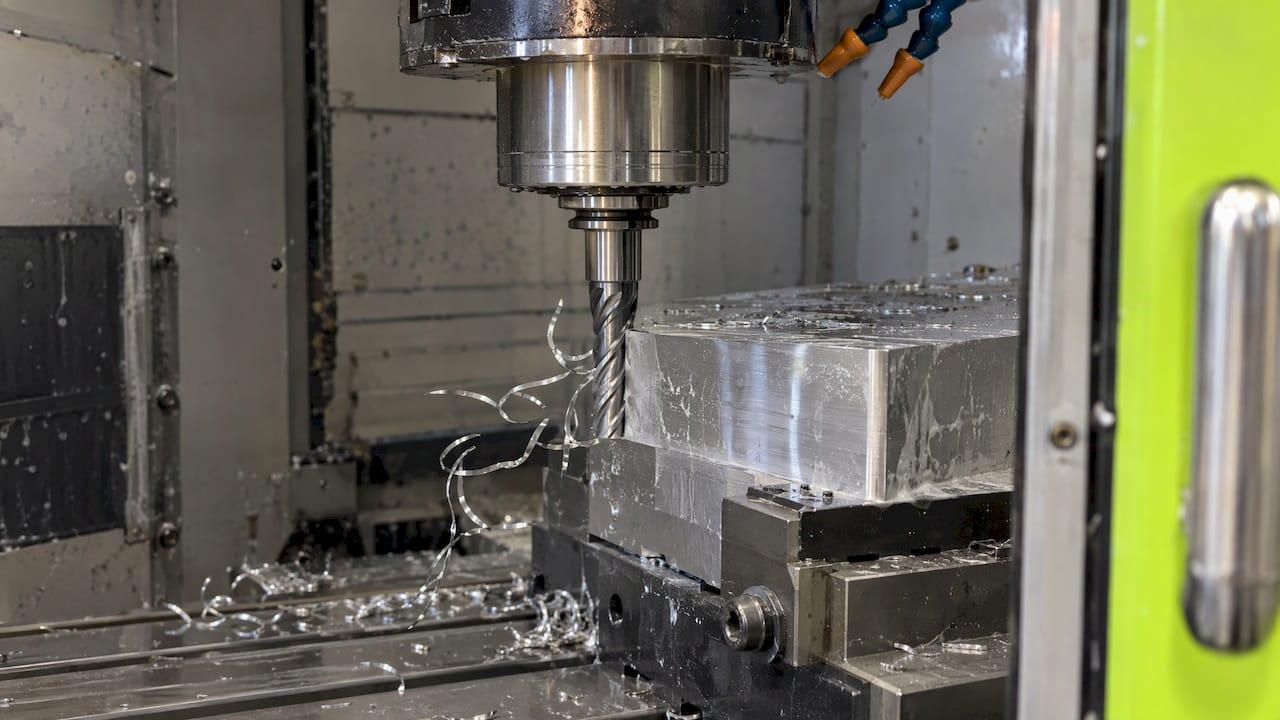
Chip thinning is what happens when your radial width of cut drops below half the cutter diameter: the chip your tool actually makes gets thinner than the feed per tooth you programmed. The fix is to raise the programmed feed by a factor based on radial engagement, so the real chip thickness matches the chip load the tool maker intended. Below, you get the formula, worked examples in inches and metric, and the limits that keep the cutter alive.
TL;DR
- Chip thinning starts when radial engagement (ae) falls below 50% of cutter diameter (D). At 50% or more, chip thickness equals programmed feed per tooth.
- The correction factor is RCTF = 1 / √(1 − (1 − 2×ae/D)²). Divide your target chip thickness by the thinning ratio, or multiply the feed per tooth by the factor.
- At 25% engagement the factor is about 1.15, at 10% about 1.67, at 5% about 2.29. Past roughly 2 to 3, cap it.
- Feeding too light rubs the edge, builds heat and wears the tool. Feeding too hard overloads corners and the machine.
- Do not apply the factor to ramping, corners or finishing passes without adjusting for them.
What chip thinning is
A milling cutter tooth cuts a chip that starts thin or thick depending on how it enters the material. In a full slot, the tooth bites in at a steep angle and the chip reaches its maximum thickness, which equals the feed per tooth. When you take a shallow side cut, the tooth leaves the material before it reaches that maximum point. Cutting Tool Engineering explains that the chip volume stays the same while the engaged cutting edge gets longer, so you get a smaller but longer chip than programmed, and a higher programmed feed is needed to restore the intended thickness.
The practical consequence: the feed per tooth in your CAM or on the tool maker's chart assumes a certain chip thickness. If your stepover is small and you leave the feed alone, the tool is cutting a thinner chip than the chart assumed. You are under-feeding it.
One distinction matters from the start. Harvey Performance Company cautions against confusing chip thickness with feed per tooth. They are the same number only at 50% engagement or more. Below that, feed per tooth is what you program, and chip thickness is what the tooth actually cuts.

When radial chip thinning starts
The threshold is half the cutter diameter. Kennametal's technical information states that the actual chip load equals the programmed chip load only when 50% or more of the diameter is engaged. Anything less reduces the real chip load by some percentage.
Sandvik Coromant lists three situations where feed per tooth can be raised because of chip thinning:
- Straight-edge cutters with an entering angle below 90°.
- Round or large-radius inserts at small depths of cut.
- Peripheral milling at small radial engagement (ae/De under 50%).
This covers a lot of everyday work. Any time you run light-stepover side milling, contouring with a finishing allowance, or a high-efficiency toolpath, you are in thinning territory.
How fast the effect grows
The correction is gentle near 50% and steep near zero. ATH Tools notes that while ae/D stays above 0.25 the correction is modest, but once it drops below 0.10 the feed must rise by close to a factor of two. That steepness is the reason trochoidal and other high-efficiency strategies run at such high feed values.
Here is the factor at common engagement levels, calculated from the formula in the next section:
| Radial engagement (ae/D) | Thinning factor | Feed increase needed |
|---|---|---|
| 50% | 1.00 | None |
| 40% | 1.02 | 2% |
| 25% | 1.15 | 15% |
| 15% | 1.40 | 40% |
| 10% | 1.67 | 67% |
| 5% | 2.29 | 129% |
| 2% | 3.57 | 257% |
The formula
The radial chip thinning factor (RCTF), valid for ae/D up to 0.5, is given by ATH Tools as:
RCTF = 1 / √(1 − (1 − 2×ae/D)²)
The equivalent form is RCTF = D / (2×√(ae×(D − ae))). The Machining Doctor calculator page uses the same expression, with adjusted feed per tooth equal to RCTF times the chip load. KEVOS writes it from the chip's side: maximum chip thickness is fz × 2 × √(ae/D − (ae/D)²) when engagement is under half the diameter, and equals fz once engagement reaches D/2.
Two things to keep straight:
- ae and D must be in the same unit. The factor is a ratio, so it is identical in inches and millimeters.
- D is the effective cutting diameter. For a flat end mill it is the nominal diameter. For ball-nose cutters the effective diameter depends on axial depth, and the Helical Solutions guidebook gives Deff = 2 × √(ADOC × (D − ADOC)).
Quick mental check
You do not need a calculator for a sanity check. Use the table above: 10% stepover means roughly 1.7 times the feed per tooth. If your corrected number is wildly different, recheck the units.
Worked examples
Imperial: ½ in end mill, light side cut
Take a ½ in end mill with a 0.050 in stepover and a target chip thickness of 0.003 in per tooth.
- ae/D = 0.050 / 0.500 = 0.10.
- RCTF = 1 / (2 × √(0.1 × 0.9)) = 1 / 0.6 = 1.67.
- Programmed feed per tooth = 0.003 × 1.67 = 0.0050 in per tooth.
- For a four-flute cutter at 6,000 rpm, feed = 0.0050 × 4 × 6,000 = 120 in/min.
Without the correction, the same setup would feed at 0.003 × 4 × 6,000 = 72 in/min. That is the 67% you were leaving on the table.
Metric: 10 mm four-flute carbide, 1 mm stepover
ATH Tools works this case: a 10 mm four-flute carbide end mill at 1 mm radial engagement (10% of D) with a target chip thickness of 0.05 mm. The factor is 1.67, so programmed feed per tooth becomes 0.083 mm, and table feed comes to roughly 1,270 mm/min at 3,820 rpm.
Metric: 16 mm cutter, 2 mm stepover
In KEVOS's example, a Ø16 four-flute carbide end mill at 2 mm radial width (12.5% of D) has a chip thickness factor of 0.661. A target chip thickness of 0.08 mm calls for 0.121 mm per tooth. That gives 1,733 mm/min and a removal rate of 69.3 cm³/min, against 1,146 mm/min and 45.8 cm³/min uncorrected.

What it does for cycle time
ISCAR's calculator guide shows a case where actual radial chip thickness was 0.078 mm against a recommended 0.13 mm. Raising feed per tooth to 0.22 mm increased material removal rate by 69%. These are supplier case studies with their own tooling and materials, so treat them as an illustration of scale, not a promise for your machine.
Converting between inch and metric
No conversion of the factor is needed. Because it depends only on ae/D, a 0.500 in cutter at 0.050 in stepover and a 12.7 mm cutter at 1.27 mm stepover have the same factor, 1.67.
Convert only the inputs and outputs:
- Chip load: mm per tooth ÷ 25.4 gives in per tooth.
- Feed rate: mm/min ÷ 25.4 gives in/min.
- Cutter diameter and stepover: convert both with the same factor, or leave both in the same unit.
The most common error is mixing a stepover in millimeters with a diameter in inches, which produces a ratio that is off by 25.4 times and a factor that is meaningless.
Limits and checks before you raise the feed
The factor tells you what feed matches a chip thickness. It does not tell you the machine, tool or setup can handle that feed. Run through these checks.
Start from a sensible chip load
UNSW Making advises confirming that the original feed per tooth is appropriate at 50% width of cut before you apply the factor. If the baseline is already aggressive, multiplying it sets the feed too fast. Choosing a chip load is a rating decision, much like forklift capacity selection: you size to the real load on the tool, not to the biggest number on the label.
Respect the force on each tooth
A higher feed per tooth means more force on each tooth. KEVOS warns that very light engagement can call for feeds that overload cutter corners or exceed the machine's feed limits, and that suppliers often publish maximum corrected feeds. Check the tool maker's ceiling.
Cap the multiplier
Engineer Underground recommends capping the multiplier at 2 to 3 in practice. Its example is a finishing pass with a 0.2 mm stepover, which would need 3.9, so a finishing pass uses a fixed small feed per tooth instead. Treat that as a shop rule of thumb, not a standard.
Do not feed too light, either
The opposite error is just as real. KEVOS describes a chip that is too thin making the edge rub rather than cut, which generates heat, can work-harden some materials, and wears the tool faster than a heavier, correct chip. Sandvik Coromant calls a thin chip with too low a value the most common cause of poor performance and low productivity, while too high a value overloads the edge and can cause breakage. If a light cut squeals and rubs, the usual cause is a feed per tooth set too low with no thinning correction.
Handle ramping and corners separately
There is no chip thinning during ramping, so UNSW Making advises not raising the ramp feed when you apply the factor. Inside corners are the other trap. Gorilla Mill notes that engagement and angle jump sharply in corners, which causes chatter. Slow the feed there or use a constant-engagement toolpath. If chatter shows up anyway, our milling chatter shop fixes cover where to look next.
Heat is not the enemy you might expect
Craig Segerlin of Performance Tooling Solutions says that in high-efficiency milling, heat is actually reduced because each edge is engaged briefly and spends more time cooling in the air. In his example, a 0.500 in cutter at 0.250 in radial width and 0.002 in chip load needs 0.007 in chip load, 3.5 times higher, when radial width drops to 0.010 in, to keep 0.002 in of real chip thickness. Chip evacuation still matters at those feeds, and our guide on chip evacuation and coolant is a good companion.
Where chip thinning pays off most
The biggest gains come where stepover is small and depth is large: contouring walls, pocketing with adaptive paths, and cleaning up with light radial passes. UNSW Making gives typical high-efficiency stepovers of 5% to 20% of diameter for aluminum and 1% to 5% for steel. In those ranges the factor runs from about 1.15 to over 2 for aluminum, and higher for steel, which is why capping and machine limits matter.
Two other cases are worth knowing:
- Thin walls. Light radial cuts help control deflection, but the feed shift is part of a larger strategy. See our notes on thin wall machining feed rates.
- Tough materials. Titanium punishes rubbing, so correct chip thickness matters. Our titanium machining guide covers how to keep the cut clean.
Slotting is the opposite case: at full width there is no thinning and no correction, as our slot machining guide explains.
David Conigliaro wrote in Cutting Tool Engineering that many programmers fear raising the feed after a bad past experience, even though radial chip thinning offers well-established productivity benefits that are still not widely applied. The answer to that fear is the checklist above: correct, cap, and treat corners and ramps as separate cases.
A repeatable routine at the machine
- Get the tool maker's recommended chip load for the material at full engagement.
- Compute ae/D with both values in the same unit.
- If ae/D is 0.5 or higher, use the chart feed per tooth as is.
- Below 0.5, compute the RCTF and multiply feed per tooth by it.
- Check the result against the tool maker's maximum, your machine's feed limit and a multiplier cap of about 2 to 3.
- Calculate feed rate: feed per tooth × flutes × rpm.
- Reduce or rework the feed for ramps, entries and inside corners.
- Listen to the first pass. Rubbing and squeal mean too light, and a heavy load or chatter means back off.
Perspective
At our shop, chip thinning is not a theory topic. We design and machine our own parts, including the E2 Kickstand for electric mini dirt bikes, and the same machinist who programs a toolpath is the person who answers your questions. That shortens the loop between a feed that looks right on paper and a surface that actually comes off the machine right.
What we have learned is that a correct chip load pays twice: it protects the tool and it protects the part. When a job calls for tight fit and a clean finish, such as a bracket, a fixture or a prototype that has to mate with something real, a light, rubbing cut is not a saving. We would rather set the feed correctly once and let the cutter do honest work.
If you are sending us a prototype or a short run, send the geometry and the material, and we will handle the process decisions directly with you, with no sales layer between you and the person at the machine.
Drake
Need the part made, not just the math?
If you would rather hand the machining to a shop that thinks about feeds and engagement every day, we handle prototype machining, short-run production, and fixtures, brackets and support parts from our shop in Athens, Alabama. You work directly with the machinist. Send us a STEP file, which our guide on STL versus STEP for CNC explains, and describe what the part has to do.

Riding an electric mini bike? Our CNC-machined E2 Kickstand fits the KTM SX-E 2, GASGAS MC-E 2 and Husqvarna EE 2, and is listed at $100-$105. For machining projects, start at flyingchipfactory.com and tell us what you need.
FAQ
Does chip thinning apply to full slotting?
No. At 50% radial engagement or more, the actual chip thickness equals the programmed feed per tooth, so there is nothing to correct. The effect begins only when radial engagement falls below half the cutter diameter, per Gorilla Mill.
Do I use the same factor for inches and millimeters?
Yes, as long as stepover and diameter use the same unit. The factor depends only on the ratio ae/D, so it is unitless. Only the chip load and feed values need converting, by dividing millimeter values by 25.4 to get inches.
How much can I raise the feed rate?
As much as the factor says, up to what the tool, machine and setup can handle. Suppliers often publish maximum corrected feeds, and one practical shop rule is to cap the multiplier at 2 to 3, according to Engineer Underground. Check the tool maker's limit first.
Is axial chip thinning a real thing?
It depends on the tool. For ball-nose cutters, axial depth changes the effective diameter and the chip thickness. For feed mills and chamfer cutters, Machining Doctor says the effect comes from the approach angle rather than axial depth, so the usual name is misleading.
Sources
- Chip Thinning, Cutting Tool Engineering (May 2005)
- How to Combat Chip Thinning, Harvey Performance Company
- Kennametal technical information
- Entering angle and chip thickness, Sandvik Coromant
- Chip thinning: radial, axial and feed correction, ATH Tools
- Milling: feed per tooth, chip thinning and feed rate, KEVOS
- Chip Thinning: Calculators and Formulas, Machining Doctor
- Machining Guidebook, Helical Solutions
- User Guide for Radial Chip Thinning Calculator, ISCAR
- Advanced CNC Milling: Feeds and Speeds, UNSW Making
- Chip Thinning, Gorilla Mill
- Chip Load, Chip Thinning and Engagement, Engineer Underground
- Limited Engagement, Cutting Tool Engineering (July 2011)
- Reaping benefits of radial chip thinning, Cutting Tool Engineering (March 2014)
- Forklift capacity selection guide