
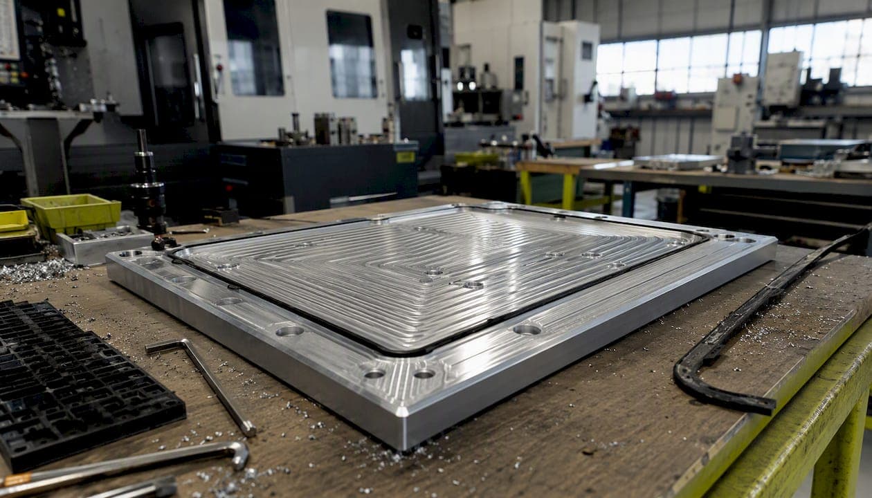
Vacuum fixture design means sealing a known surface area against a plate and using atmospheric pressure to press the workpiece down with real, calculable clamping force. That's the whole concept. No mechanical clamps, no bolted straps, just air pressure doing the work once you've pulled a vacuum underneath a sealed part.
Here's the number that matters most: A commonly used vacuum level produces a practical, moderate clamping pressure. Multiply that by your sealed area and you get pounds of force. A 12-by-13-inch plate at that vacuum level generates over 1,500 pounds of holding force, enough for plenty of light-to-moderate milling operations. Always calculate against the final sealed area, meaning the surface area remaining after your part design removes material, pockets, or through-holes. Design against raw stock dimensions and you'll get an optimistic number that doesn't survive the last operation.
Five things to nail down before you cut metal:
- Surface prep — flatness and finish on both the plate and the part determine whether your seal holds at all.
- Seal type — O-ring groove, cord gasket, or foam pad, chosen for the part's geometry and material.
- Grid zoning — isolate areas the part doesn't cover so you're not wasting pump capacity on open channels.
- Pump capacity — match CFM to your total sealed volume and expected leak rate, not just plate size.
- Mechanical assists — dowel pins or edge stops to handle the lateral forces vacuum alone can't resist.
If your production run is more than a handful of parts, or your plate size and pump requirements are creeping past what a shop vacuum pump can handle, that's usually the point where fabricating in house stops making sense. Flying Chip Factory builds custom fixtures and runs the actual production work behind them, which means the fixture gets designed by someone who also has to run parts on it.
Key Takeaways
Vacuum fixture design works when clamping force is calculated from final sealed area, sealed with the right gasket and grid, and reinforced with mechanical assists against lateral cutting loads.
| Point | Details |
|---|---|
| Use the force formula | Clamping force equals sealed area times effective pressure, calculated against final post-machined area, not raw stock. |
| Respect the 12.3 psi benchmark | 25 inHg of vacuum delivers roughly 12.3 psi of usable holding pressure in most shop setups. |
| Choose downcut tooling | Downcut endmills push force into the table and preserve vacuum hold better than upcut geometry. |
| Add mechanical assists | Dowel pins and edge stops handle lateral force that vacuum pressure alone can't resist. |
| Outsource beyond shop capacity | Flying Chip Factory builds custom vacuum fixtures and runs the production work behind them when plate size or volume outgrows a shop build. |
How Does Vacuum Workholding Create Clamping Force?
Clamping force equals sealed area multiplied by effective pressure, in pounds per square inch. That's the entire formula, and everything else in vacuum fixture design is just refining the two variables in it.
Atmospheric pressure at sea level sits around 14.7 psi. A vacuum pump doesn't add force. It removes air from beneath the sealed part, and the surrounding atmosphere pushes down to fill that pressure differential. A vacuum chuck's maximum holding power tops out around 13 psi, roughly a ton per square foot, which is the practical ceiling you should design around rather than the theoretical 14.7 psi limit.
Here's how inHg (inches of mercury, the unit most vacuum gauges display) converts to usable psi:
- 10 inHg ≈ 4.9 psi, useful for light finishing passes on soft materials.
- 20 inHg ≈ 9.8 psi, adequate for general-purpose aluminum work.
- 25 inHg ≈ 12.3 psi, near the practical ceiling most shop pumps reach.
- 29.9 inHg ≈ 14.7 psi, theoretical perfect vacuum at sea level, which you'll never actually hit.
Run the math on a small part. A 6-by-6-inch sealed area at this vacuum level gives a moderate downward clamping force. Doubling the area to 12 by 12 inches increases the clamping force correspondingly, which is why plate size matters more than pump strength once you're past a certain point.
The catch that trips up a lot of first-time fixture builders: vacuum only resists force perpendicular to the sealed surface. It does nothing against a side-loading cutter trying to slide the part sideways. That limitation shapes almost every other decision in this guide, from tooling choice to mechanical assist placement.
How Do You Calculate Required Vacuum for a Fixture?
Required vacuum equals the clamping force you need divided by your available sealed area. Flip the equation, and required sealed area equals your target clamping force divided by the vacuum pressure your pump can reliably sustain.
Say you're machining a thin 6061-T6 aluminum plate, 10 by 8 inches, and your cutting operation generates an estimated 200 lbf of combined axial and lateral load at the tool. You want a safety margin, so you're targeting at least 600 lbf of holding force, a 3:1 ratio that's a reasonable starting point for general milling.
Your raw sealed area is 80 square inches. But this part has four 1-inch-diameter mounting holes and a center pocket removing another 6 square inches, so your final sealed area after machining drops to roughly 71 square inches. Design against that number, not the raw 80.
Required pressure is the target clamping force divided by sealed area, which corresponds to a vacuum level achievable by many shop-grade pumps. Well within range for most shop-grade vacuum pumps, which typically pull 20 to 27 inHg.
Here's a quick reference for moving between the units you'll actually use at the bench:
A more rigorous version of this same process, backed by FEA and modal analysis for thin aerospace-grade parts, shows up in published fixture design research where clamping force calculations get validated against actual deformation under load. You don't need finite element software for a bracket fixture. But the underlying logic is identical: calculate from final geometry, then verify the margin holds under real cutting loads.
What Components Does Every Vacuum Fixture Need?
Every functional vacuum fixture needs six things: a base or plenum plate, a sacrificial top plate, distribution grooves, a gasket or seal, a vacuum pump, and a valve/filter system between the pump and the plate. Skip any one of them and the fixture either doesn't seal or doesn't survive contact with a cutting tool.
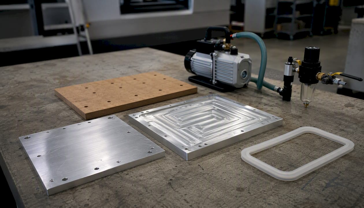
| Component | Role | Typical material | Critical spec |
|---|---|---|---|
| Base/plenum plate | Houses vacuum channels and ports | 6061-T6 aluminum, steel | Flatness within a couple thousandths |
| Sacrificial top plate | Protects grid, takes tool contact | MDF, phenolic, aluminum | Replaceable, quarter to half inch thick |
| Grooves/channels | Distribute vacuum across the area | Machined into plate | 0.125–0.250 in width |
| Gasket/seal | Creates the airtight boundary | Silicone, Buna-N, foam cord | Matches groove cross-section |
| Vacuum pump | Generates the pressure differential | Rotary vane, venturi | CFM matched to plenum volume |
| Valves/filters | Protect pump, isolate zones | Ball valves, inline filters | Sized to hose ID |
The plenum plate is where flatness tolerances actually matter. If your base plate isn't flat within a couple thousandths, you'll get localized leak paths no gasket can fully compensate for, especially on larger plates where warpage compounds across the surface.
O-ring groove geometry follows a fairly standard rule: groove depth should sit at 70 to 85 percent of the O-ring's cross-sectional diameter, which gives enough compression to seal without over-crushing the material. Channel widths and depths are selected within typical ranges to balance flow and plate strength.
Pro Tip: Always run a sacrificial top plate over your primary vacuum grid, even on a one-off job. A single tool plunge into the actual plenum plate can wreck a channel network that took hours to machine. A $40 piece of MDF or phenolic is cheap insurance against that mistake.
How Should You Design a Vacuum Grid and Port Layout?
Design your grid so no sealed point is more than a few inches from a channel, and isolate any zone your workpiece won't fully cover. A grid with excessive travel distance between the farthest point and the nearest port creates slow evacuation and uneven holding force across a large part.
For a general-purpose modular plate, these dimensions have proven reliable across a wide range of part sizes:
- Grid spacing of 1 to 2 inches between parallel channels works for most flat aluminum and composite parts.
- Channel width of 0.125 to 0.250 inch balances flow capacity against structural weakening of the plate.
- Channel depth of 0.050 to 0.100 inch keeps enough cross-section for airflow without creating a deep pocket a gasket can't bridge.
- Port thread size should match your hose barb, typically NPT fittings in the 1/8 to 1/4 inch range for small to medium plates; if you're unsure which thread standard applies, a quick NPT vs BSP comparison will save you a mismatched fitting order.
Port sizing needs to track your pump's CFM rating, not just the plate's footprint. An undersized port or hose creates a throttle effect where the pump is rated for adequate flow but the plumbing between the pump and the plate can't deliver it. If you've sized a pump for 5 CFM and you're running it through a 1/4-inch ID hose over ten feet, you'll lose real capacity to friction and restriction before that air ever reaches the plenum.
- Map your grid before you commit to port locations, working from the largest expected part inward.
- Isolate unused zones with removable cord gaskets or plug inserts rather than leaving open channels exposed to atmosphere.
- Add a secondary port on plates larger than roughly 18 by 18 inches to reduce evacuation time and improve pressure uniformity.
This kind of modular grid patterning with plug-and-play zone isolation is what lets a single plate handle a dozen different part geometries instead of building a dedicated fixture for every job. It's the single biggest efficiency gain available to a shop running varied short-run work.
What Materials Work Best for Vacuum Fixtures?
Plate material choice usually comes down to 6061-T6 aluminum for general shop fixtures or steel-backed chucks for high-volume, high-wear applications. For gaskets, silicone handles temperature swings well, Buna-N resists oils and solvents better, and closed-cell foam gasketing works fine for lower-precision, quick-turnaround jobs.
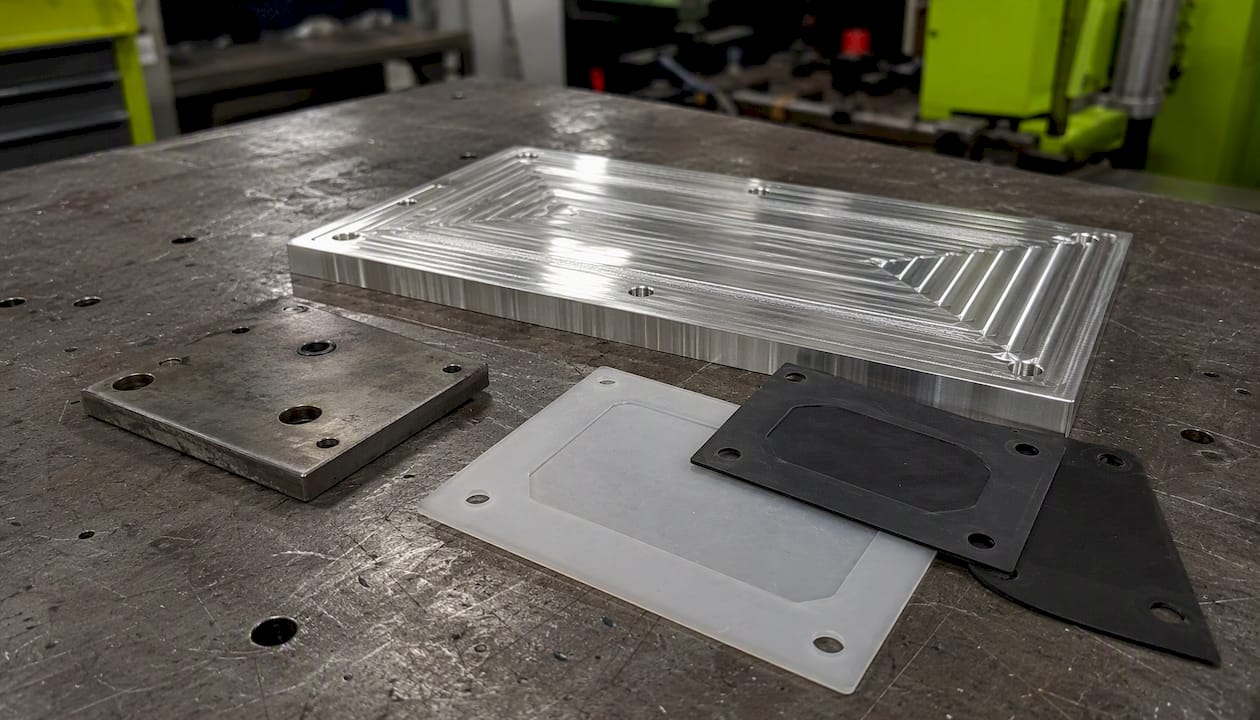
Aluminum plates machine fast, stay reasonably flat, and are easy to modify when a fixture needs revisions. If you're choosing between tempers, the difference between T6 and T6511 aluminum mostly comes down to residual stress relief, which matters more for larger plates that need to hold flatness over a wide span.
Porous materials are where vacuum fixturing runs into a hard limit. Materials like raw MDF, certain composites, and unsealed wood products don't hold vacuum well because air leaks through the material itself rather than just around its edges. Three workarounds actually solve this in a working shop:
- Backing plate method: bond or double-side-tape the porous stock to a non-porous sheet, then vacuum-hold the backing plate instead.
- Surface coating: a sealant coat or laminate skin on the porous material's underside can create enough of a barrier to hold a partial vacuum.
- Foam sponge method: a compressible foam layer between the porous part and the plate can compensate for minor surface irregularities, though it won't fix a fully porous material on its own.
Flatness and surface finish on the sealing face matter more than most people expect starting out. A rough or scratched surface, even one that looks flat to the eye, creates micro-leak paths. If you're anodizing plates for corrosion resistance, keep in mind that coating thickness changes the sealing surface geometry slightly, which is worth checking against your hardcoat anodize thickness spec before you finalize gasket dimensions.
Temperature and humidity aren't cosmetic concerns here. Cold shop air holds less moisture, which generally helps seal integrity, but temperature swings can cause differential expansion between an aluminum plate and a rubber gasket, opening tiny gaps at the boundary. High humidity environments accelerate gasket degradation, particularly with lower-grade foam seals, so a shop running in a humid climate should lean toward silicone or Buna-N over foam for anything beyond short-term prototyping.
Pro Tip: For a quick prototype seal, a bead of RTV silicone run directly into a scribed or shallow-machined channel cures fast and gives you a usable gasket in under an hour, without waiting on a custom-cut O-ring cord. Just don't machine into that channel later, since RTV doesn't clean out of a groove the way a removable cord gasket does.
Can you vacuum-hold MDF directly? Not reliably. Raw MDF is porous enough that most shop pumps can't maintain a usable pressure differential across it without a backing plate or a sealed coating on the contact face.
Does gasket material affect precision work? Yes, softer foam gaskets compress unevenly under load, which can introduce measurable part deflection on tight-tolerance jobs. Silicone or Buna-N cord in a properly sized groove gives more consistent compression.
What Are Some Shopmade Vacuum Fixture Designs?
Three patterns cover the vast majority of shop-built vacuum fixtures: the perimeter O-ring plate, the grid-chuck with channel seals, and the foam or porous-sponge backing method. Each fits a different combination of part shape, batch size, and available shop time.
- Perimeter O-ring plate: a single O-ring groove machined around the outer edge of the expected part footprint, one port, minimal internal channels. Fast to build, typically under two hours of machine time on a basic plate, and works well for single-piece or low-volume flat parts with no internal features that need isolation.
- Grid-chuck with channel seals: the full modular grid described earlier, with removable cord gaskets to isolate zones. Takes longer to build, often a full shop day including groove machining and gasket fitting, but pays that time back across dozens of future jobs with different part geometries.
- Foam/porous-sponge backing method: no machined grid at all. A foam sheet with a bonded impermeable top layer sits atop a plenum plate, and the part presses into the foam to create a seal around its own perimeter. Fastest setup of the three, useful for irregular or curved parts that won't seal against a flat gasket.
Deciding between building in-house and buying or outsourcing comes down to a few practical questions:
- Repeatability: if you're running the same fixture setup weekly for months, a purpose-built commercial vacuum table often justifies its cost faster than repeated shopmade rebuilds.
- Plate size: commercial vacuum tables handle large-format flat sheet work more consistently than a shop-built plenum plate, though they're generally better suited to lightweight material and may need extra support for heavier stock.
- Accuracy requirements: tight-tolerance production runs benefit from a fixture engineered and QC'd by a shop that also has to hold that tolerance on the finished part.
- Cost-per-part math: a shopmade jig might cost a few hundred dollars in material and machine time; a dedicated commercial vacuum table system runs well into four or five figures depending on size and pump capacity. Outsourcing fixture fabrication to a job shop typically lands somewhere between those two, scaled to job complexity.
For anything beyond a quick prototype fixture, that's usually the point in the conversation where it's worth getting Flying Chip Factory involved, since building the fixture and running the actual production parts under the same roof tends to catch design issues before they become expensive mistakes.
Which Tooling Choices Keep a Part From Lifting?
Prefer downcut endmills whenever you're cutting on a vacuum-held part. A downcut tool's flute geometry pushes chips and axial force downward into the table, which reinforces the vacuum's holding force instead of fighting it.
Upcut tools do the opposite. Their flute geometry pulls the workpiece upward as it cuts, directly opposing the vacuum's downward clamp. On a marginal setup, an upcut tool can be the difference between a stable cut and a part that lifts mid-operation. Shop-tested guidance on vacuum workholding consistently points to downcut tooling as the safer default for anything held primarily by vacuum.
Beyond tool selection, a few cutting strategy choices reduce risk further:
- Take lighter finish passes with reduced stepover on the final surface pass, since a heavy finishing cut generates more lateral load right when the part has the least remaining material to resist it.
- Favor smaller-diameter cutters on thin or delicate stock, since larger cutters generate proportionally higher lateral forces per pass.
- Consider climb milling (conventional relative to tool rotation direction) carefully on vacuum-held parts, since the direction of cutting force interacts with how the part wants to shift under lateral load.
Vacuum alone rarely resists significant lateral cutting force, so mechanical assists earn their place on almost every real production fixture. Dowel pins dropped into two or three locating holes stop rotational and lateral drift without adding much setup time. Edge stops along one or two sides of the part do similar work for rectangular stock. Temporary tabs, small uncut bridges left in the toolpath, are a common trick for parts with thin or unsupported sections that need extra stability through a roughing pass.
Pro Tip: Sequence your operations so the roughest, highest-force cuts happen first while the part still has maximum sealed surface area, and save your finest finish passes for last, after most of the lateral load has already been removed from the process. If you're machining features that reduce your sealed area significantly, like large pockets or through-slots, check your slot machining sequencing so you don't accidentally drop below your required holding force before the job is done.
How Do You Test and Troubleshoot a New Vacuum Fixture?
Test a new fixture with a four-step protocol: a vacuum gauge check, a time-to-vacuum measurement, a known-weight hold test, and monitoring during a simulated cut. Skipping straight to production without this sequence is how shops discover leak problems mid-job, which is a far more expensive way to find out.
- Vacuum gauge check: confirm the pump reaches its rated inHg with the fixture sealed but no part loaded, establishing your baseline before any part variable enters the picture.
- Time-to-vacuum measurement: place a part, seal it, and time how long it takes to reach working pressure. A time that creeps up over repeated tests usually signals a developing leak or filter clog.
- Known-weight hold test: with a part sealed and held only by vacuum, apply a known lateral force (a spring scale works fine) to verify your calculated clamping force roughly matches what the fixture actually delivers.
- Simulated cut monitoring: run an air-cut cycle (no material removal) while watching the vacuum gauge for pressure drops that would indicate a developing leak once real cutting forces are introduced. A time-to-vacuum and known-weight lift test paired with pressure monitoring during a simulated cut is a genuinely effective early-warning system for catching problems before they show up as a scrapped part.
When a fixture that used to work starts underperforming, work through this checklist in order:
- Check the gasket for nicks, compression set, or debris trapped along the seal line, which is the most common cause of a sudden leak.
- Clear grooves and channels of chips or dust, since even fine debris can create a leak path around a gasket that's otherwise in good shape.
- Inspect inline filters for clogging, particularly on fixtures used with materials that generate fine dust.
- Confirm hose ID hasn't been swapped for something undersized during a repair, which throttles flow even with a healthy pump.
- Test pump performance independently of the fixture to rule out declining pump condition versus a fixture-side problem.
A basic maintenance schedule prevents most of these issues before they start: check gaskets weekly on high-use fixtures, replace foam or cord seals showing visible compression every few months, and follow the pump manufacturer's oil and service intervals rather than running it until it fails.
Pro Tip: If a fixture that held fine for months suddenly starts leaking, check the gasket and grooves before you assume the pump is failing. A worn gasket is a five-minute fix; tearing into a grid redesign because you assumed the fixture itself was wrong wastes hours chasing the wrong problem.
Vacuum Fixture Checklist and Pump Sizing Chart
A shop-ready vacuum fixture template is a single-sheet checklist with fields for final sealed area, anticipated cutting force, required vacuum, pump CFM, sealing method, and mechanical assists. Filling this out before you touch the mill turns a guessing exercise into a five-minute calculation.
The sheet needs six fields, in this order: part final sealed area (square inches, post-machining), anticipated peak cutting force (lbf), required vacuum pressure (psi and inHg), pump CFM rating against total plenum volume, sealing method selected, and a checkbox list of mechanical assists planned (dowel pins, edge stops, tabs).
Pump sizing tracks roughly with sealed area, though total plenum volume and expected leak rate shift the numbers:
| Sealed area range | Recommended pump CFM | Reservoir/plenum note |
|---|---|---|
| Less than 50 square inches | 3–5 CFM | Small plenum, single port sufficient |
| 50 to 150 square inches | 5–8 CFM | Add secondary port for even distribution |
| 150 to 300 square inches | 8–12 CFM | Consider a vacuum reservoir tank for stability |
| Over 300 sq in | 12+ CFM | Dual pumps or zoned grid recommended |
Reservoir volume should run at least three times your pump's displacement for reasonably fast evacuation without excessive pump cycling. A standard 12-by-12-inch modular plate works well with grid spacing at 1.5 inches, channel width at 0.1875 inch, and a single centered port with NPT threading sized to match your hose.
Pro Tip: Print the checklist and laminate it. A one-page reference taped near the vacuum pump saves more rework than any amount of memorized formulas, especially when a new hire is running the fixture for the first time. You can build a similar reference structure using the same checklist and template approach Flying Chip Factory uses for gauge documentation.
When a job calls for a fixture beyond what this template covers, whether that's plate sizes over 24 inches, production volumes in the hundreds, or geometries too irregular for a modular grid, that's the point to bring in Flying Chip Factory for custom fixture fabrication, either as a standalone build or bundled with the production run itself.
Should You Build Your Own Vacuum Fixture or Buy One?
Build your own fixture for prototyping, one-off jobs, or low part counts where flexibility matters more than throughput. Buy a commercial system or outsource fixture fabrication once repeatability, plate size, or production volume outgrows what a shop-built jig can reliably deliver.
The decision usually turns on a handful of concrete factors:
- Part complexity: simple flat geometries fit shopmade grid patterns easily; irregular or curved parts often need custom fixture engineering.
- Repeatability need: a fixture that has to perform identically across hundreds of cycles benefits from tighter tolerances than most shop builds achieve on the first pass.
- Available shop resources: if your shop doesn't already have spare mill time, gasket stock, and a qualified pump on hand, the "cheap" DIY option starts looking less cheap once you count sourcing time.
- Cost-per-part threshold: run the math on fixture amortization against your expected part volume; a $300 shopmade jig amortized over five parts costs a lot more per part than the same jig amortized over five hundred.
If your project is sitting right at that threshold, plate size pushing past shop pump capacity, tolerances tighter than a shopmade fixture reliably holds, or a production run large enough that fixture failure mid-batch would be expensive, that's the case for treating fixture fabrication as its own line item. Flying Chip Factory builds fixtures alongside the production parts that run on them, which closes the gap between a fixture design that looks good on paper and one that survives real cutting loads.
A Machinist's View on Vacuum Fixture Failures
Most vacuum fixture problems don't come from bad math. They come from designing against the wrong surface area. A part that pockets out 30 percent of its raw stock area partway through a job doesn't care what your holding force calculation looked like when the stock was solid. It cares what the sealed area looks like at the exact moment the heaviest cut happens, which is usually somewhere in the middle of the job, not the beginning.
The fix isn't more vacuum. It's sequencing. Rough the features that reduce sealed area last if you can get away with it, or add mechanical assists before you start rather than after the part shifts and you're staring at a scrapped piece. A lot of shops treat dowel pins and edge stops as an afterthought, something you add after a part moves once. They should be part of the first design pass, not the repair.
The other pattern worth calling out: shops that size a pump for the plate instead of the plenum volume. A big plate with a lot of internal channel volume needs a reservoir or a higher-CFM pump to evacuate fast enough, even if the sealed area itself is modest. Undersized pumps aren't usually a strength problem, they're a speed problem, and that shows up as a part that seats fine at rest but loses grip the moment a roughing pass generates real heat and vibration.
A vacuum-held part machined right, with the sequencing and mechanical assists dialed in, holds tolerance as well as most mechanically clamped setups, without the clamp marks, without the repositioning between operations, and with full top-surface access for the tool. That's the actual argument for vacuum fixturing. Not that it's easier, but that it's better once it's designed correctly.
Get Custom Vacuum Fixtures Built Right the First Time
Reading a formula and cutting a working fixture aren't the same skill, and a lot of the failures covered in this guide come down to details that only show up once metal starts moving. Flying Chip Factory works directly with the machinist handling your job, not a sales layer between you and the person cutting the part, so a fixture revision happens in a phone call instead of a week-long email chain.

That direct line matters most when a fixture design needs a quick iteration mid-project, a groove pattern that needs adjusting, a port relocated, a mechanical assist added after a first test run reveals a weak spot. Flying Chip Factory handles vacuum fixture fabrication for prototype and short-run CNC work, along with the production machining that fixture is built to support, so the same shop that designs your holding solution is the one accountable for the parts coming off it. If your next job needs a custom vacuum fixture, a production run, or both, get a quote from Flying Chip Factory and describe your part geometry, expected cutting forces, and volume so the fixture gets sized right from the start.
Frequently Asked Questions About Vacuum Fixture Design
What is the maximum clamping force a vacuum fixture can achieve? Most shop vacuum systems top out around 13 psi of effective holding pressure, close to the theoretical atmospheric limit of 14.7 psi. That translates to roughly 1,500 lbf on a modest 12-by-13-inch sealed area at 25 inHg.
Can vacuum fixtures hold porous materials like MDF? Not directly. Porous materials leak air through the material itself, not just around the edges, so a backing plate, surface coating, or foam sponge method is required to create a usable seal.
Do vacuum fixtures resist sideways cutting forces? No. Vacuum only produces downward clamping force perpendicular to the sealed surface. Lateral forces from milling operations need mechanical assists like dowel pins or edge stops.
Should I use downcut or upcut tooling on a vacuum-held part? Downcut tooling is the safer default, since it pushes axial force into the table and reinforces the vacuum's hold. Upcut tools pull the part upward and increase the risk of losing suction mid-cut.
When does it make sense to outsource vacuum fixture fabrication? Once plate size, pump capacity, tolerance requirements, or production volume exceed what a shop-built jig can reliably deliver, outsourcing to a job shop like Flying Chip Factory typically costs less per part than repeated in-house rebuilds.
Sources
A handful of sources go deeper on specific pieces of this guide, worth a look if you want the underlying data behind a particular calculation or technique.
- Workholding With A Vacuum Chuck | Modern Machine Shop
- Vacuum Workholding | Welch Vacuum
- Vacuum Workholding Tips & Tricks
- Vacuum chucks, fixtures, and clamping: CNCCookbook
- Vacuum Chuck Fixture Design — Industrial Monitor Direct