
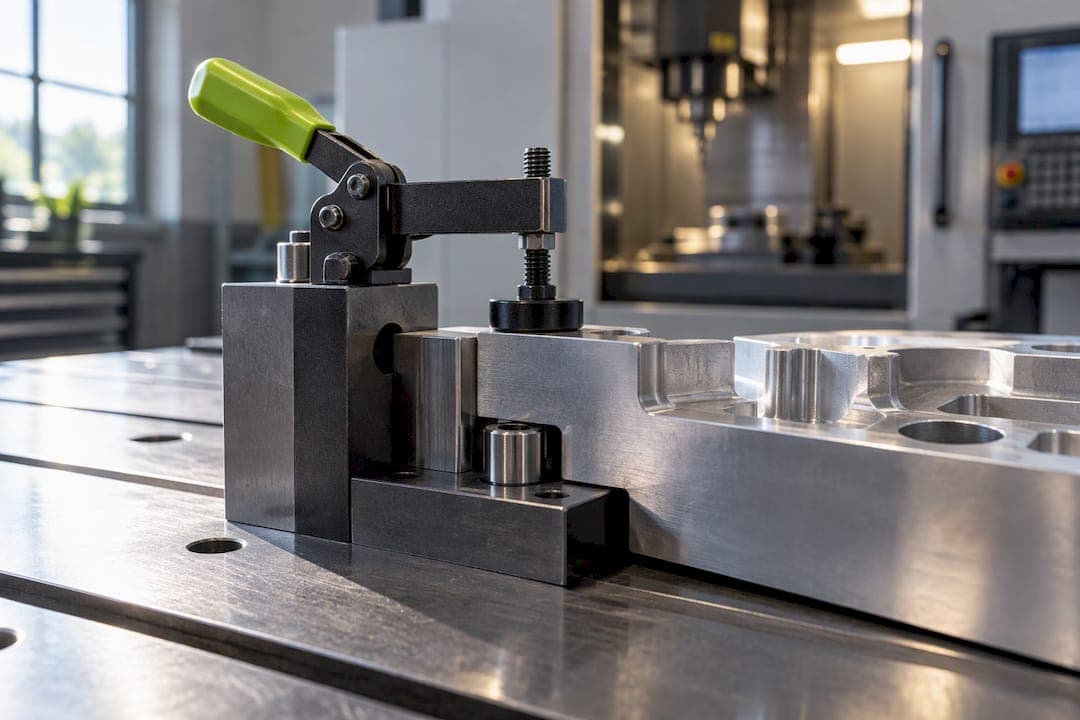
A fixture is a workholding device that deterministically locates, supports, and clamps a workpiece so machining, welding, inspection, or assembly can happen with repeatable accuracy. Unlike a jig, a fixture never guides the cutting tool itself. The core rule of fixture design basics never changes: locate first, support second, clamp last. Skip that order and the part moves, distorts, or seats differently every cycle.
TL;DR:
- Proper fixture design relies on the correct sequence: locate first, support second, and clamp last to ensure repeatability and prevent distortion during processing.
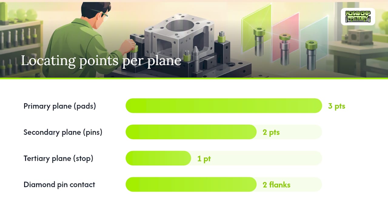
- The 3-2-1 locating principle uses three points on a primary plane, two on a secondary, and one on a tertiary surface to fully constrain a part's six degrees of freedom accurately.
- Fixtures should be made with hardened, replaceable contact surfaces, and clamps should apply only necessary force to avoid deforming or damaging lightweight or thin parts.
- Maintaining fixture accuracy requires routine inspection of locator tips, re-verification of clamp torque, and documentation of wear and calibration over time.
- Custom fixtures from vendors like Flying Chip Factory incorporate the 3-2-1 logic, replaceable wear surfaces, and detailed documentation to ensure long-term precision and upgradability.
Fixture Design Basics: Locate, Support, Clamp
Locate, support, and clamp sound like three words for the same job. They are not, and confusing them is the single most common mistake beginners make in fixture design.
Locating establishes the fixed relationship between the part and the machine. Locators are the reference points that set position and orientation, and they answer one question only: where does this part sit? Supports come next. They carry the weight of the part and resist the forces of the operation itself, whether that's a cutting tool pushing down or a weld shrinking a joint. Clamps come last, and their only job is to hold the part against the locators, not to define where the part goes.
Beginners routinely get this backward. They clamp first, then let the part "find its own way" into position. The result is inconsistent seating from one cycle to the next, and if the clamp squeezes an unsupported span, the part bends elastically, gets machined out of true, then springs back distorted once the clamp releases. SME's training material draws this distinction directly: locators establish the tool-to-workpiece relationship, while clamps only secure it.
A few habits separate reliable fixtures from unreliable ones:
- Locators contact the part first and never move once set.
- Clamping force always points toward a locator or a supported region, never toward open air.
- Supports sit directly under any zone taking cutting or clamping load.
- Clamp pressure gets checked against part stiffness, not just against holding the part still.
Pro Tip: If you can loosen a clamp and the part shifts even slightly, your locators aren't doing their job. A correctly located part shouldn't move when clamping pressure is removed.
The 3-2-1 Locating Principle in Practice
A rigid part in space has six degrees of freedom: three translations along the X, Y, and Z axes, and three rotations around them. The 3-2-1 locating principle eliminates all six with a specific distribution of contact points, and it's the backbone of practical fixture design.
- Primary plane, three points. Three locators on the largest, most stable surface remove three degrees of freedom: Z-translation and rotation around the two horizontal axes.
- Secondary plane, two points. Two locators against a perpendicular surface remove Y-translation and rotation around Z.
- Tertiary plane, one point. One locator against a third surface removes the final degree, X-translation.
On a prismatic block, that usually means three flat pads under the bottom face, two shoulder pins against one side, and one stop pin against the end. On a round part, swap the pads and pins for a V-block pair plus a single stop pin against a shoulder or face. Irregular castings often need custom-machined nests that mimic the same three-plane logic even when no flat surface exists.
One frequent error: using two identical round locating pins where a diamond or relieved pin belongs. Two round pins can fight each other across a hole-to-hole tolerance and over-constrain the part. Swapping one for a diamond pin that only touches on two flanks lets the part settle without binding.
Choosing Between Modular and Dedicated Fixture Types
Fixtures split into categories by the operation they support: machining fixtures resist cutting forces, welding fixtures hold parts through heat and shrinkage, inspection fixtures hold geometry steady for a gauge or CMM, assembly fixtures align mating components, and marking fixtures just need to hold a part still for a stamp or laser. Each demands a different balance of rigidity, access, and thermal tolerance, and Stratasys breaks these operational categories down clearly.
The bigger decision most engineers face early is dedicated versus modular tooling:
- Dedicated fixtures are simpler, cheaper per unit, and ideal for a single part number running in volume.
- Modular fixtures cost more upfront but amortize across part families and change over faster.
- Common fixture bodies include base plates, tombstones, faceplates, and angle plates, each suited to different machine tool geometries.
- Product families with frequent variation almost always favor modular over dedicated setups.
Shops running high-mix, low-volume work lean modular almost by default. For a deeper breakdown of reuse strategies, Flying Chip Factory's guide to modular fixturing walks through when the upfront cost actually pays off.
Fixture Components: Locators, Clamps, and Materials
Every fixture element carries its own selection logic, and getting the material wrong shows up as scrap long before anyone diagnoses the root cause.
Locators need hardened, replaceable tips. A soft locator wears into a rounded profile within weeks of production use, and once that happens, part position drifts silently. Tooling balls work well for round or spherical reference features; V-blocks handle cylindrical stock; flat buttons handle machined pads. Surface finish matters more than most beginners expect. A locator finished to a rough Ra invites debris to pack against the contact face, which throws off repeatability just as much as wear does.
Clamp selection depends on volume and force. Toggle clamps suit manual, low-volume work where an operator needs fast load and unload. Toe clamps distribute force over a wider footprint for thinner stock. Hydraulic and pneumatic clamps dominate production because they deliver repeatable force without operator variation.
- Clamps should apply the minimum force needed to resist cutting load, gravity, and inertia.
- Excessive clamp force deforms thin or compliant parts, even when the part looks fine once released.
- Supports belong directly beneath any zone taking clamp or cutting load, never off to the side.
Clamp force is a budget, not a maximum. Every newton beyond what's needed to resist the operation's forces is a newton available to bend the part. That single reframe changes how most engineers approach clamp selection once they internalize it.
A Step-by-Step Fixture Design Sequence
A repeatable design process saves more debugging time than any single locator trick. The sequence below mirrors the practical workflow ToolingU teaches in its fixture design coursework, adapted for shop use.
- Study the part and the operation. Know exactly what forces the fixture must resist and what features can serve as reference surfaces.
- Identify the datums. Pull reference surfaces straight from the part drawing so the fixture ties directly to the part's tolerance scheme.
- Choose a fixture body. Base plate, angle plate, tombstone, or faceplate, matched to the machine and the operation.
- Place the locators. Apply 3-2-1 logic, adjusted for the part's actual geometry.
- Add supports. Position them under load-bearing zones, not just wherever there's open space.
- Select clamps. Choose type and force based on the part's stiffness and the operation's cutting or process loads.
- Check access and clearance. Confirm the tool path, chip evacuation, and coolant flow all clear the fixture body.
- Verify in CAD or FEA. Confirm stiffness and repeatability before cutting metal.
Build in a loading path an operator can't get wrong. A pin that only fits one orientation, or a fixture body that's asymmetric on purpose, prevents a misload that a rushed second-shift operator would otherwise make at 2 a.m.
Pro Tip: Before releasing a new fixture to production, run a first-article check: load the part, measure it in place if possible, then unload and remeasure. If the numbers shift more than your tolerance allows, the fixture needs revision before it touches a real job.
Shop-Proven Lessons on Fixture Maintenance
Textbook fixture theory gets you to a working design. Keeping that design accurate for the next 10,000 cycles is a different skill, and it's the one that separates shops with clean scrap rates from shops guessing why a part drifted.
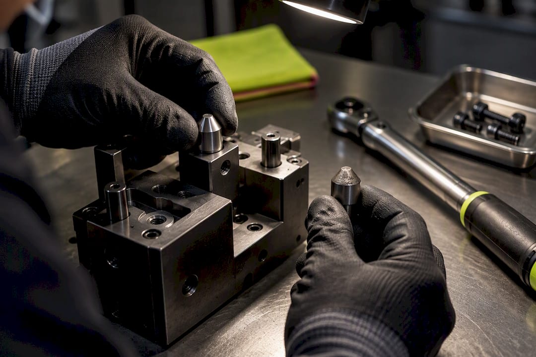
Documentation is the first line of defense. Every fixture built gets a drawing that records locator positions, a fixture ID tied to the CNC program that runs against it, torque specs for every clamp, and the setup order an operator follows. Linking that record to the program itself means anyone on the floor can trace a dimensional problem back to a specific fixture revision instead of guessing.
Wear shows up quietly. Locator tips should be replaceable by design, and datum surfaces need scheduled checks, not just a look when something already went wrong.
- Inspect locator tips on a fixed cycle count, not on an "if it looks worn" basis.
- Track torque specs at every clamp point and re-verify after any fixture rebuild.
- Escalate to FEA once a part gets thin, flexible, or the deflection budget starts closing in on the tolerance band.
A fixture that passed first-article inspection six months ago is not guaranteed to pass it today. Wear is cumulative and often invisible until a dimension finally drifts out of spec.
Verifying and Maintaining Fixture Accuracy
Verification isn't a one-time event at fixture handoff. It's a recurring routine that catches drift before it reaches a customer's part.
Load and unload checks confirm the part seats the same way every time, and a simple go/no-go gauge catches gross errors fast. For inspection fixtures specifically, CMM references give a tighter, traceable baseline than a manual gauge ever will.
A practical maintenance schedule includes:
- Cleaning locating surfaces between shifts to prevent chip and coolant buildup from throwing off contact.
- Replacing worn tips on a defined interval rather than waiting for a scrap part to flag the issue.
- Re-checking clamp torque after any rebuild or long production run.
- Logging calibration dates so drift is traceable across the fixture's service life.
Rigid-body assumptions eventually run out of runway. Research on fixture-layout stability treats deformation, reaction forces, and natural frequency as real design constraints, not edge cases, and calls for FEA once those factors move past a hand-calculation. Thin walls, compliant sections, and high-speed operations are the usual triggers. Flying Chip Factory's guide to tight tolerance machining covers how tolerance budgets and verification routines interact once you're chasing single-digit-thousandths repeatability.
Fixture Design Standards and Best Practices Worth Following
No single regulatory body issues a universal fixture design standard the way ISO governs threads or ASME governs pressure vessels. What exists instead is a set of well-tested conventions that most competent shops converge on independently, because they're the conventions that actually prevent scrap.
The 3-2-1 locating principle functions as the closest thing to an industry standard, and it shows up in nearly every serious fixture design curriculum for a reason: it's the minimum geometry that fully constrains a rigid part without over-constraining it. Beyond that, best practice generally includes designing for a single, unambiguous loading orientation, specifying hardened and replaceable wear surfaces at every contact point, and dimensioning the fixture directly from part datums rather than from convenient fixture geometry.
Material specification matters more than many designers assume. Fixture bodies typically run mild steel or aluminum for cost and machinability, while locators and wear surfaces get hardened tool steel, often case-hardened or through-hardened depending on expected cycle count. Surface finish on wear points should be specified explicitly, not left to "whatever the mill leaves behind," because a rough locating surface degrades repeatability faster than almost any other single variable.
A written checklist beats memory every time: confirm datum scheme, confirm 3-2-1 distribution, confirm clamp force against part stiffness, confirm tool and coolant access, and confirm the fixture has been verified in CAD or on the machine before it goes into rotation. Shops that skip the checklist in favor of "the designer already knows this stuff" are the ones that eventually scrap a batch over a locator nobody rechecked.
Estimating Cost and Budget for a New Fixture
Fixture cost breaks into three buckets: design time, raw material and hardware, and machining time to build the fixture itself. Underestimating any one of them is how a "quick fixture" job quietly eats a week.
Design time scales with part complexity and tolerance. A simple base plate with three pads and a stop pin might take an experienced designer an hour to lay out. An irregular casting needing a custom nest with diamond pins and multiple support points can take considerably longer, especially if CAD verification or FEA gets involved.
Material and hardware costs depend heavily on volume expectations. A one-off prototype fixture can run on mild steel with off-the-shelf toggle clamps. A production fixture running tens of thousands of cycles justifies hardened locating inserts, pneumatic or hydraulic clamping, and a more robust body, all of which raise the bill of materials but pay it back in reduced downtime and rework.
The real budgeting question isn't "how much does this fixture cost," it's "how does fixture cost compare to the cost of not having one." A dedicated fixture that shaves two minutes off every setup on a 500-part run pays for itself fast. A modular fixture that gets reused across five part families amortizes even faster; Flying Chip Factory's breakdown of quick-change fixturing payback walks through exactly that kind of return calculation. Budget for the fixture as a production tool with a payback period, not a sunk cost.
Safety Considerations Every Fixture Design Must Address
A fixture that fails mechanically during a cutting or welding operation is a safety event, not just a scrap event, and that risk needs to be designed out from the start.
Clamping force is the first safety variable. A clamp sized only to "hold the part still" without margin for cutting forces, vibration, or an operator bumping the setup can release mid-cycle. Hydraulic and pneumatic clamps need pressure monitoring or fail-safe checks so a line pressure drop doesn't silently release a part while a spindle is still turning.
Sharp edges, exposed pinch points, and moving clamp mechanisms need guarding or at minimum clear operator awareness, especially on manual toggle-clamp setups where hands are close to the mechanism during load and unload. Fixture bodies that project into the tool's travel path create a collision risk that's easy to miss in a rushed setup, which is why checking clearance against the full tool path, not just the finished part geometry, belongs in every design review.
Orientation errors carry their own risk profile. A fixture that only fits the part one way, sometimes called poka-yoke design, prevents an operator from loading a part backward or upside down, a mistake that can send a tool into a clamp or fixture body at full feed rate. Weight matters too: fixtures over a manageable lift weight need integrated lifting points or a documented handling procedure, not an assumption that whoever's on shift will figure it out.
Case Studies: How Fixture Design Plays Out on Real Parts
Abstract principles land differently once you see them applied to an actual part geometry.
Take a small aluminum bracket destined for an electric mini dirt bike drivetrain, the kind of part Flying Chip Factory machines regularly. The part has a flat mounting face, one bolt-pattern side, and a curved edge that offers no clean flat reference. The 3-2-1 approach here uses three pads under the flat face for the primary plane, two shoulder pins against the bolt-pattern side for the secondary plane, and a single stop pin against a machined tab for the tertiary plane. Clamping happens directly over the pad zone, never near the curved edge, because that edge has no support beneath it and would deform under pressure.
Contrast that with a cylindrical shaft-style part. Two V-blocks handle the primary and secondary constraint simultaneously, since a V-block naturally locates two degrees of freedom per contact pair, and a single stop pin against an end face or shoulder finishes the six-degree-of-freedom lockout. This geometry comes up constantly in motorcycle component work, from axles to linkage pins, where round stock dominates.
A third case worth noting: fixtures built for small electric-vehicle components, whether a mini dirt bike part or a light utility vehicle bracket like those Boson Motors builds toward, often share the same challenge of low part mass paired with tight tolerance. Low mass means clamping force margins are especially easy to overshoot, since it takes very little pressure to distort a light aluminum bracket. That combination, more than sheer part complexity, is usually what separates a fixture that works from one that quietly ruins a production run.
What the Textbooks Get Right, and What They Skip
The textbook version of fixture design, the 3-2-1 principle, the locate-support-clamp sequence, the tidy CAD verification step, is correct as far as it goes. Where it falls short is in treating fixture design as a one-time event instead of a system that degrades from the first cycle onward.
Most engineering coursework spends enormous time on getting the initial layout right and almost none on what happens to that layout after 5,000 cycles of thermal expansion, chip abrasion, and operator handling. That's a real gap, because in shop practice, more scrap comes from a worn locator nobody flagged than from a bad initial 3-2-1 layout. The fixtures that hold tolerance longest aren't necessarily the most elegantly designed ones. They're the ones with a torque spec written down, a replaceable tip instead of a hardened permanent one, and a documented check interval someone actually follows.
The other place conventional advice undersells itself is FEA. Plenty of guidance frames finite element analysis as an advanced step reserved for exotic geometry. In practice, any part with a thin wall, a long unsupported span, or a tolerance band under a couple thousandths benefits from at least a basic contact-element check, because rigid-body assumptions quietly stop being true well before most designers think to question them.
If there's one habit worth prioritizing above the others, it's building the verification and maintenance plan at the same time as the fixture itself, not after the first batch of scrapped parts forces the conversation.
— Drake
Get Fixtures Built by a Shop That Designs for Repeatability
Reading about locate, support, and clamp is one thing. Getting a fixture built that actually holds tolerance for thousands of cycles is another, and that's where Flying Chip Factory's shop experience closes the gap between theory and the floor. Every fixture, bracket, or support part that leaves Flying Chip Factory's shop in Athens, Alabama, is designed and machined by the same person who answers your questions, with no sales layer slowing down revisions between design and cut metal.

Flying Chip Factory's fixtures, brackets, and support parts service covers exactly the kind of workholding this article walks through: 3-2-1 locating logic applied to your actual part geometry, replaceable wear surfaces, and documentation you can hand to an operator on day one. If you're prototyping a new part or scaling a short production run and need a fixture that won't drift after the first hundred cycles, that's a direct conversation with the machinist, not a quote form disappearing into a queue. And if your project is a finished part rather than tooling, the E2 Kickstand for KTM SX-E 2, GASGAS MC-E 2, and Husqvarna EE 2 shows the same fixture-driven precision applied to a bolt-on production part. Pricing details are on the Flying Chip Factory website. Get in touch through Flying Chip Factory's site to start a quote on your next fixture or prototype job.
Sources
- SME fixture-design study guide
- Fixture design for CNC machining — UTEC
- Designing jigs and fixtures — Vention
FAQ
What are the basic principles of fixture design?
The three non-negotiable principles are locate, support, and clamp, applied in that order. Locators fix the part's position, supports carry operational loads, and clamps only secure the part against the locators rather than defining its position.
What is the 3-2-1 principle in fixture design?
The 3-2-1 principle eliminates all six degrees of freedom using three contact points on a primary plane, two on a secondary plane, and one on a tertiary plane. It's the standard method for fully constraining a rigid part without over-constraining it.
How do you design a fixture?
Start by studying the part and its operation, then pull datums from the drawing, choose a fixture body, place locators using 3-2-1 logic, add supports under load zones, select clamps, and check tool access before verifying stiffness in CAD. This ordered sequence comes directly from established fixture design coursework and holds up across most part types.
What are the three types of fixtures?
Fixtures are usually grouped by operation rather than a fixed count of three, covering machining, welding, inspection, assembly, and marking applications. Each category demands different rigidity and access requirements based on the forces and precision the operation involves.
Does Flying Chip Factory build custom fixtures?
Yes. Flying Chip Factory offers fixtures, brackets, and support parts as part of its CNC machining services, alongside prototype machining and short-run production, with pricing available on request through its service page.