
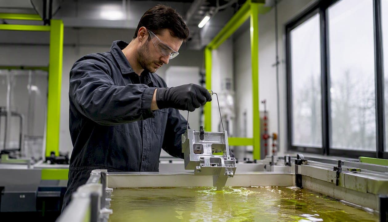
Electroless nickel (EN) can be applied to aluminum reliably, but only when the native oxide is removed and the surface receives proper activation before plating begins. Skip that step, and the deposit peels. Get it right, and you have a uniform, wear-resistant nickel-phosphorus coating that holds tight tolerances on complex geometry. The single most proven activation route is the double-zincate process, and the short recommendation for your drawing note is this: require double-zincate pretreatment or an approved zincate-free electropretreatment, specify deposit class and phosphorus range, and mandate adhesion and salt-spray test reports with each lot.
Key references that govern this work:
- ISO 1456 and ISO 1458 for appearance and corrosion-resistance requirements on nickel deposits
- SAE AMS-QQ-N-290 for class, grade, and thickness designations and verification methods
- Products Finishing technical guidance for aluminum-specific pretreatment best practices
Key Takeaways
Electroless nickel on aluminum succeeds or fails at the pretreatment stage: double-zincate remains the most reliable activation method, and every other variable is secondary to getting that step right.
| Point | Details |
|---|---|
| Double-zincate is the default | Specify double-zincate pretreatment on drawings for all 2xxx, 5xxx, and 7xxx alloys; single-zincate is acceptable only for non-critical 1xxx/3xxx applications. |
| Phosphorus content drives properties | Specify medium-P (6–9%) for general wear; high-P (10–13%) for corrosion resistance or post-plate hardening above 1000 HV. |
| Thickness determines use class | 12–25 µm for corrosion protection; 25–75 µm for engineering build-up; account for bilateral dimensional change on all mating features. |
| Galvanic risk requires attention | Zinc interlayers are anodic to nickel; require nickel-immersion pretreatment for parts in aggressive or humid service environments. |
| Flying Chip Factory | Provides plating-ready CNC machining with drawing-note support, masking planning, and sample-coupon handling for EN on aluminum jobs. |
Why do engineers choose electroless nickel on aluminum?
Aluminum's strength-to-weight ratio is hard to beat, but bare aluminum wears fast, corrodes in salt environments, and solders poorly. Electroless nickel fixes all three without adding much weight or changing part geometry significantly.
The functional benefits that drive EN selection on aluminum:
- Uniform thickness on complex geometry. Unlike electroplating, EN deposits by chemical reduction with no line-of-sight dependency. Bores, undercuts, and blind pockets plate to nearly the same thickness as external faces, which matters for molds, connectors, and hydraulic bodies.
- Build-up and dimensional restoration. Undersized machined parts can be brought back to nominal with a controlled EN deposit. A plater can target a specific thickness and hold it within a few tenths of a mil.
- Wear resistance. Medium-phosphorus Ni–P (6–9% P) offers solid as-deposited hardness. After heat treatment at 400°C, high-phosphorus deposits can reach hardness values that rival hard chrome on steel, making EN a practical choice for sliding wear surfaces and mold cores.
- Solderability and brazeability. Bare aluminum solders poorly. An EN deposit gives a solderable surface for electronic connectors, RF shields, and fuel-system fittings.
- Customizable hardness via phosphorus content. You can dial in the tradeoff between hardness and corrosion resistance by specifying the phosphorus range, which is something anodize cannot offer.
Typical application sectors include injection mold tooling, aerospace fuel-system components, electronic connector housings, sliding wear surfaces in automotive assemblies, and repair/build-up of undersized shafts or bores.
Anodize is the better call when scratch resistance and decorative appearance are the primary drivers, or when dimensional change must be kept under 0.0001 inches per surface. Anodize also costs less per part in most job shops. EN makes sense when the part needs uniform coverage, build-up, or a solderable surface. For a detailed look at anodize thickness specifications and how they compare to EN on dimensional control, the hardcoat anodize thickness guide is a useful companion reference.
Pro Tip: If your part has both threaded features and sliding wear surfaces, specify EN on the wear surfaces and mask the threads, or plan for post-plate thread chasing. Plating build-up inside a threaded bore will kill fit.
Why plating aluminum is harder than plating steel
Steel has a stable oxide that a simple acid etch removes cleanly. Aluminum's oxide reforms in seconds when exposed to air or water, and that fresh oxide layer bonds to nothing. That is the core problem, and every failure mode in EN on aluminum traces back to it.
The oxide problem and activation timing. Aluminum forms Al₂O₃ almost instantly on a clean surface. If any step in the pretreatment sequence takes too long, or if the part dries between steps, the oxide is back and adhesion is compromised. Timing between activation and EN immersion is measured in seconds, not minutes.
Galvanic risk from the zinc interlayer. The zincate process deposits a thin zinc layer that displaces the oxide and gives EN a nucleation surface. The problem is that zinc is anodic to nickel. If the EN deposit develops porosity or a pinhole, zinc at the interface acts as a sacrificial anode in humid or corrosive environments, driving lateral corrosion that lifts the nickel film from the inside out. Products Finishing documents this mechanism and notes it is one reason double-zincate is preferred over single-zincate: the strip-and-reapply cycle produces a finer, more uniform zinc layer with fewer coarse particles that later dissolve and create interface voids.
Common process-related failure modes to plan for:
- Bath contamination. Aluminum dissolves into the EN bath over time, raising aluminum ion concentration and destabilizing the bath. Bath monitoring and turnover schedules are non-negotiable.
- Excessive etch or pitting. Over-etching in the alkaline clean or acid activation step creates surface pits that trap chemistry and become porosity nucleation sites.
- Porosity in blind features. Trapped air or solution in blind holes prevents uniform wetting during zincate and EN steps. Part orientation and agitation during immersion matter.
- Hydrogen entrapment. EN deposits, especially high-phosphorus amorphous layers, can trap hydrogen during deposition. Post-plate baking at 190–200°C relieves hydrogen embrittlement; for encapsulated parts, a slow temperature ramp is needed to avoid blistering.
- Poor coverage in deep slots or narrow channels. Solution exchange is limited in tight features; deposition rate drops and the deposit may be thinner or discontinuous.
Surface pits, tool marks deeper than 32 µin Ra, or residual cutting fluid in blind holes will show up as adhesion failures after plating. Fixing the surface before plating costs far less than a rejected lot.
How do the main pretreatment methods compare?
The pretreatment choice is the single biggest variable in EN on aluminum. Get it wrong and no amount of bath chemistry optimization saves the deposit.
Double zincate: the gold standard
The double-zincate sequence runs: alkaline clean → acid etch → first zincate immersion → nitric acid strip → second zincate immersion → immediate EN immersion. The strip-and-reapply step is the key. The first zincate deposits a coarse, non-uniform zinc layer. Stripping it in dilute nitric acid exposes a fresh aluminum surface, and the second zincate deposits a finer, more uniform zinc film with better coverage. Research on multiple alloys including A1100, A2017, A5052, and A7075 confirms that double zincate generally improves adhesion strength across alloy classes, though alloying elements like copper and zinc in the base metal materially affect outcomes and must be factored into the activation chemistry.
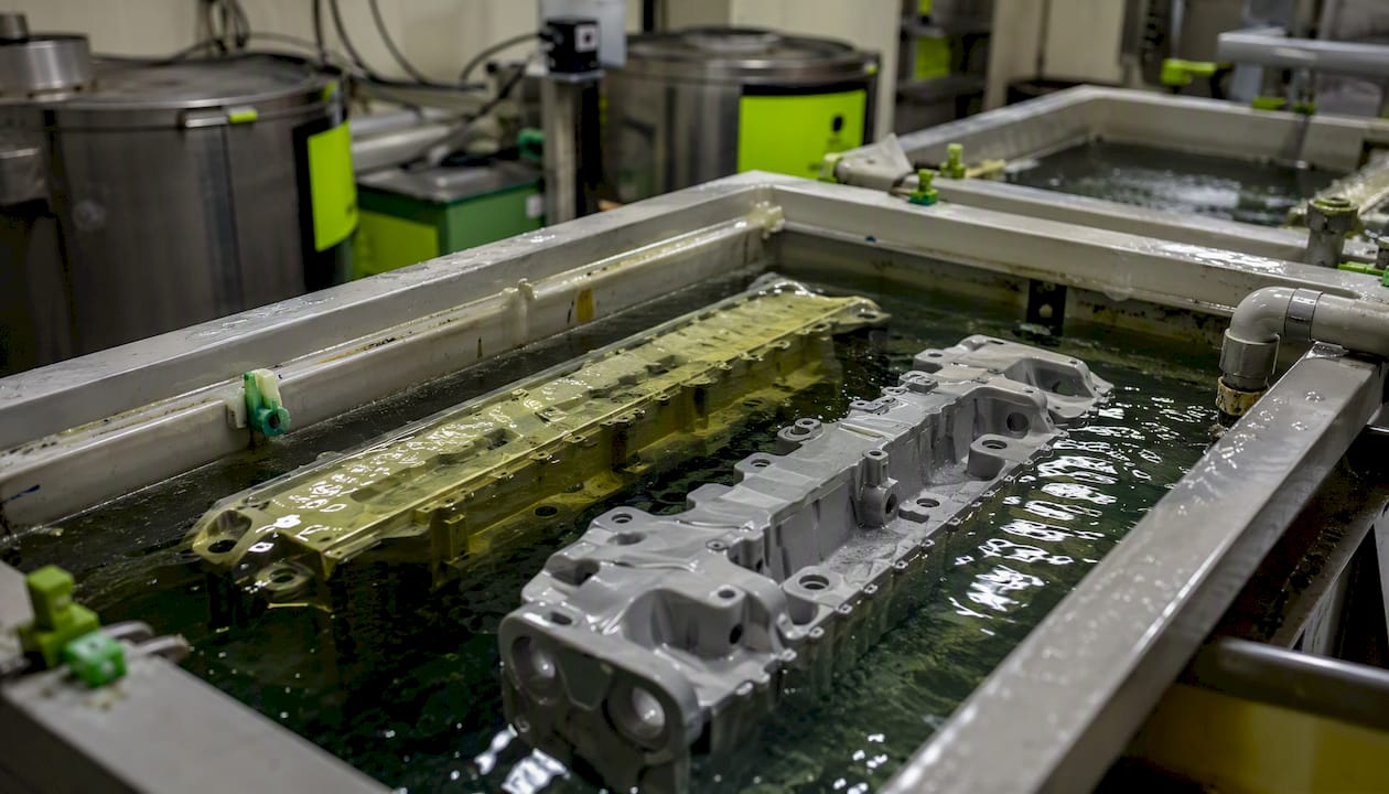
Commercial-grade zincate formulations are more consistent than custom mixes because they control nucleation density across alloy grades, reducing coarse zinc particles that later dissolve and create interface gaps.
Other pretreatment options
- Single zincate. Faster and cheaper, but produces a coarser zinc layer with higher porosity risk. Acceptable for non-critical corrosion applications on pure aluminum or 1xxx/3xxx series alloys. Not recommended for 2xxx or 7xxx series or any application requiring long-term corrosion resistance.
- Nickel immersion pretreatment (NIP). Replaces zinc with a nickel displacement layer. Studies show that double nickel-immersion pretreatment improves corrosion resistance of Ni–P coatings compared with no pretreatment and can be developed into a double-immersion process analogous to double-zincate. Eliminates the galvanic risk from the zinc interlayer, which makes it worth considering for parts in aggressive service environments.
- Zincate-free electropretreatment. Pulse-reverse electropretreatment has been demonstrated at bench scale for direct Ni or Ni–P deposition on 6061 without zincate, reducing process steps and hazardous chemical use. A zincate-free route has also been validated for aluminum bond pads in microelectronic applications using a simplified etch/rinse/plate sequence with good adhesion. Both approaches require strict vendor process validation before use on production parts.
| Pretreatment method | Adhesion reliability | Galvanic risk | Contamination risk | Environmental footprint | Tight-tolerance suitability | Recommended alloys |
|---|---|---|---|---|---|---|
| Double zincate | High | Moderate (Zn interlayer) | Low with commercial formulation | Moderate (Zn/NaOH waste) | Good | Most alloys; verify on 2xxx/7xxx |
| Single zincate | Moderate | Moderate | Higher | Moderate | Acceptable for non-critical | 1xxx, 3xxx series |
| Nickel immersion (double) | Moderate to high | Low (no Zn) | Low | Lower Zn waste | Good | Corrosion-critical applications |
| Zincate-free electropretreatment | Demonstrated; requires validation | Very low | Low | Lower hazardous waste | Good for microelectronics | 6061; validate per alloy |
When to require vendor qualification testing: any new alloy, any safety-critical application, any switch from double-zincate to an alternate method. Acceptance tests should include a 90° bend or peel adhesion test and a minimum salt-spray exposure per the applicable standard before production release.
How does phosphorus content change the deposit?
Electroless nickel is not a single material. The bath chemistry, specifically the phosphorus or boron concentration, determines what you actually get on the part.
Ni–P deposit variants
Ni–P is the dominant commercial system. Phosphorus content divides into three practical ranges:
- Low-P (1–4% P). Crystalline microstructure, highest as-deposited hardness (roughly 550–650 HV), ferromagnetic. Used where hardness matters more than corrosion resistance. Less common on aluminum because the bath chemistry can be aggressive toward the zincate layer.
- Medium-P (5–9% P). Mixed crystalline/amorphous structure. Good balance of hardness (450–550 HV as-deposited) and corrosion resistance. The most common choice for general engineering applications on aluminum.
- High-P (10–13% P). Fully amorphous, non-magnetic, best as-deposited corrosion resistance. As-deposited hardness is lower (400–500 HV), but heat treatment at 400°C can push hardness above 1000 HV. Ni–P deposit properties depend strongly on phosphorus content and heat treatment, with high-P deposits giving superior corrosion resistance and heat treatment enabling substantial hardness increases used in tooling applications.
Ni–B deposits
Nickel-boron (Ni–B) deposits offer higher as-deposited hardness than Ni–P (often 650–750 HV) and a different heat-treatment response. They are used in applications demanding maximum hardness without post-plate heat treatment, such as precision tooling and wear-critical connectors. Ni–B baths are less common and more expensive to maintain.
| Deposit type | As-deposited hardness | Corrosion resistance | Heat-treat response | Magnetic | Typical use case |
|---|---|---|---|---|---|
| Low-P Ni–P (1–4%) | 550–650 HV | Moderate | Modest increase | Yes | High-hardness, non-corrosive environments |
| Medium-P Ni–P (5–9%) | 450–550 HV | Good | Moderate increase | Weakly | General engineering, wear surfaces |
| High-P Ni–P (10–13%) | 400–500 HV as-dep; >1000 HV post-HT | Excellent | Large increase | No | Corrosion-critical, mold tooling |
| Ni–B | 650–750 HV | Moderate | Moderate | Weakly | Maximum hardness without heat treat |
Bath operating conditions also matter for aluminum specifically. Acidic EN baths (pH 4.5–5.0) are standard for Ni–P. Alkaline EN baths (pH 8–10) are used for Ni–B and some specialty applications. Acidic baths can partially dissolve a thin or poorly applied zincate layer during the initial deposition phase, which is one reason bath pH control is a critical parameter to monitor and document.
What thickness should you specify?
Nickel plating thickness on aluminum follows two broad use-case categories: corrosion protection and engineering build-up. The ranges below reflect common industry practice.
- Corrosion protection class (light service): 5–12 µm (0.2–0.5 mil). Adequate for mild environments, indoor hardware, and decorative-functional parts. Porosity risk increases below 5 µm.
- Corrosion protection class (moderate to severe service): 12–25 µm (0.5–1.0 mil). Standard for aerospace and automotive corrosion applications. Provides meaningful barrier protection when the deposit is continuous and pore-free.
- Engineering build-up / wear class: 25–75 µm (1.0–3.0 mil). Used for dimensional restoration, mold surfaces, and sliding wear applications. At this range, post-plate grinding or lapping is sometimes needed to hit final tolerances.
- Heavy build-up: 75–125 µm (3.0–5.0 mil). Repair and salvage applications. Expect significant dimensional change; machine after plating.
SAE AMS-QQ-N-290 provides class and grade designations for nickel deposits that map to these ranges and specify verification methods. For drawing notes, a compact spec call-out looks like this:
- Corrosion class: "Electroless nickel per AMS-QQ-N-290, Class 1, 12–25 µm (0.5–1.0 mil) min, double-zincate pretreatment, adhesion and salt-spray test report required."
- Engineering/wear class: "Electroless nickel per AMS-QQ-N-290, Class 2, 25–50 µm (1.0–2.0 mil), medium-P (6–9% P), double-zincate pretreatment, post-plate bake 190°C/1 hr, thickness map and adhesion test report required."
Dimensional change is bilateral: EN deposits on all surfaces, so a bore that is 1.000 inches in diameter will shrink by twice the deposit thickness (one deposit on each wall). A 25 µm deposit reduces a bore diameter by 0.002 inches. Machine critical bores and mating features to allow for this, or plan to post-plate ream. For threaded features, the same logic applies; see the NPT vs BSP thread spec guide for how thread tolerances interact with post-process finishing.
What process steps and control parameters should you require from your plater?
A well-run EN line on aluminum follows a defined sequence with documented parameters at each step. Here is what that sequence looks like and what you should be asking your plater to control and record.
Process sequence
- Alkaline soak clean — removes oils, cutting fluids, and loose contamination. Temperature: 60–70°C, 5–10 minutes.
- Rinse — deionized or high-purity water, two-stage cascade preferred.
- Acid etch / desmut — removes surface oxides and smut from alloying elements. Typically dilute nitric or sulfuric acid, 20–30°C, 30–60 seconds. Over-etching causes pitting.
- Rinse.
- First zincate immersion — 20–25°C, 30–60 seconds. Commercial formulation preferred.
- Nitric acid strip — removes first zinc layer, 50% HNO₃, 15–30 seconds.
- Rinse.
- Second zincate immersion — same conditions as first. Produces finer, more uniform zinc layer.
- Rinse — immediate transfer to EN bath.
- EN deposition — acidic Ni–P bath, pH 4.5–5.0, temperature 85–92°C, deposition rate 10–25 µm/hr. Time calculated for target thickness.
- Rinse — two-stage.
- Dry — forced air or oven at 60–80°C.
- Post-plate bake (if required) — 190–200°C for hydrogen relief; 380–400°C for hardness increase (high-P deposits).
Critical control parameters
| Parameter | Typical range | Why it matters |
|---|---|---|
| EN bath temperature | 85–92°C | Controls deposition rate and deposit structure |
| EN bath pH | 4.5–5.0 (acidic Ni–P) | Affects deposition rate and zincate stability |
| Deposition rate | 10–25 µm/hr | Determines plating time for target thickness |
| Phosphorus content (bath) | Per deposit spec (low/med/high P) | Sets deposit hardness and corrosion resistance |
| Aluminum ion concentration | Monitor; replace bath at limit | Excess Al³⁺ destabilizes bath and causes roughness |
| Zincate immersion time | 30–60 sec per step | Over-immersion produces coarse zinc; under-immersion leaves gaps |
| Post-plate bake temperature | 190–200°C (H₂ relief) or 380–400°C (hardening) | Hydrogen relief prevents blistering; hardening increases HV |
Incoming inspection checklist for plated aluminum parts
- Visual: no blistering, peeling, pitting, or bare spots under 10x magnification
- Thickness: XRF or coulometric measurement at a minimum of 5 points per part (include recesses if accessible)
- Adhesion: 90° bend test or cross-hatch tape test per applicable standard on a sample coupon from the same lot
- Salt spray: sample coupon from each lot, minimum hours per drawing requirement
- Phosphorus content: confirm with plater's bath records or request XRF analysis on a coupon
Which standards and tests belong on your drawing?
Citing the right standards on a drawing or purchase order is what makes acceptance criteria enforceable. Vague notes like "nickel plate per industry standard" are not enforceable.
Core standards for EN on aluminum:
- ISO 1456 / ISO 1458 — requirements for nickel electrodeposition, including appearance and corrosion-resistance expectations. ISO 1456 covers decorative nickel; ISO 1458 covers engineering nickel. Both are standard references for appearance and corrosion performance.
- SAE AMS-QQ-N-290 — class and grade designations, thickness requirements, and verification methods for nickel deposits. The NASA PRC-5004 process specification references AMS-QQ-N-290 language and is a useful model for purchase-order language.
- ASTM B733 — standard specification for autocatalytic (electroless) nickel-phosphorus coatings; covers service condition classes, thickness, and test methods specifically for EN.
- ASTM B117 — salt-spray test method. Specify hours on the drawing (e.g., 96 hours, 240 hours, 500 hours) based on service environment.
- ASTM B571 — adhesion test methods including bend test, file test, and thermal shock.
- ASTM B568 — XRF thickness measurement method.
| Test | Failure mode detected | Typical acceptance threshold |
|---|---|---|
| 90° bend / peel (ASTM B571) | Adhesion failure, delamination | No peeling or flaking after bend |
| Salt spray (ASTM B117) | Corrosion resistance, porosity | No base-metal corrosion at specified hours |
| XRF thickness (ASTM B568) | Under/over-deposit | Within ±10% of specified range at all measurement points |
| Cross-hatch tape test | Adhesion, cohesion | No removal of deposit on tape |
| Visual inspection | Blistering, pitting, bare spots | Zero defects under 10x magnification |
Test per ASTM B571 (bend), ASTM B117 (240 hr salt spray), ASTM B568 (XRF thickness). Submit test report with each lot."
Troubleshooting common EN failures on aluminum
Most EN failures on aluminum trace to one of four root causes: inadequate activation, bath chemistry drift, process timing errors, or part geometry issues. Here is how to diagnose and correct each.
Adhesion failure (peeling or blistering):
- Root cause: oxide not fully removed before zincate; zincate layer too coarse or non-uniform; delay between zincate and EN immersion.
- Diagnosis: peel test on a sample coupon; examine the failure interface (aluminum side vs zinc side indicates where the break occurred).
- Corrective action: verify zincate immersion time and chemistry; switch to double-zincate if using single; reduce time between zincate strip and EN immersion to under 30 seconds; confirm bath pH is within range.
Porosity and pitting:
- Root cause: over-etching in acid activation; contaminated bath; insufficient agitation in blind features.
- Diagnosis: coulometric porosity test or ferroxyl test on a sample coupon.
- Corrective action: reduce acid etch time; check bath aluminum ion concentration; increase agitation or rotate part during deposition; consider post-plate sealing for corrosion-critical applications.
Lateral corrosion (nickel lifting from edges or pinholes):
- Root cause: zinc interlayer acting as anode in humid service; porosity allowing electrolyte ingress.
- Diagnosis: cross-section metallography at the failure site; look for zinc depletion at the interface.
- Corrective action: switch to nickel-immersion pretreatment to eliminate the zinc interlayer; specify higher-P deposit for better barrier properties; increase deposit thickness.
Nodules or rough surface:
- Root cause: bath contamination (particulates, decomposition products); excessive bath age; poor filtration.
- Corrective action: continuous bath filtration (1–5 µm filter); monitor bath turnover; replace bath at end of rated life.
QA and acceptance actions
- Establish a sample coupon program: include one or two coupons of the same alloy in every plating run, processed identically to production parts.
- Require batch traceability: plater documents bath age, temperature log, pH log, and zincate lot number for each run.
- Periodic adhesion and salt-spray sampling: test one coupon per lot for adhesion; test one coupon per batch for salt spray at the specified hours.
- Bath parameter control logs: request copies with each delivery; flag any run where temperature or pH fell outside the specified range.
Fixture and masking tips:
- Mask threaded bores and precision fits with plugs or tape rated for the bath temperature (85–92°C).
- Orient blind holes downward or agitate to prevent air lock during immersion.
- Use titanium or plastic fixtures; steel fixtures contaminate the EN bath.
- For slot-machined features, verify that slot width allows adequate solution exchange; slots narrower than 2:1 depth-to-width ratio may plate unevenly.
EN vs anodize vs other coatings: which one fits your application?
The choice between EN and anodize comes down to what the part actually needs to do.
EN wins when: the part needs uniform thickness on complex geometry, dimensional build-up, a solderable surface, or wear resistance that anodize cannot match. Activation and surface preparation are the decisive factors for adhesion quality, and when those are controlled, EN on aluminum performs reliably in demanding service environments.
Anodize wins when: scratch resistance and decorative appearance are primary, dimensional change must be minimal (Type II anodize adds roughly 0.0001 inches per surface), or cost is the dominant constraint. Hard anodize (Type III) offers excellent abrasion resistance but adds more dimensional change than Type II and can crack at sharp corners.
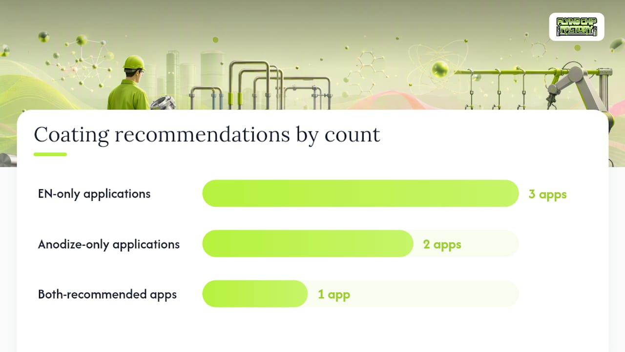
| Application priority | Recommended coating | Reason |
|---|---|---|
| Wear resistance, sliding surfaces | EN (medium-P, heat treated) | Hardness >1000 HV post-HT; uniform on complex geometry |
| Corrosion resistance, severe environment | EN (high-P) or hard anodize | High-P EN: excellent barrier; anodize: lower cost |
| Electrical contact / solderability | EN | Solderable surface; anodize is an insulator |
| Decorative, architectural | Anodize (Type II) | Color options, lower cost, minimal dimensional change |
| Dimensional build-up / repair | EN | Controlled thickness; anodize cannot build up |
| Tight dimensional tolerance, no build-up | Hard anodize or Type II | Predictable, thin, well-characterized dimensional change |
Two concrete examples: injection mold cores in 7075 aluminum benefit from EN with post-plate heat treatment because the hardened deposit resists abrasion from filled polymers and the uniform coverage protects complex cavity geometry. Architectural aluminum panels, on the other hand, belong in an anodize line: the color range, lower cost, and minimal dimensional change make EN unnecessary and expensive for that application.
Zincate-free and electropretreatment approaches lower the hazardous waste footprint compared to conventional zincate processes. A novel pulse-reverse electropretreatment has been shown to enable direct Ni–P deposition on 6061 with reduced chemical use, though vendor process validation is required before production adoption.
Pre-plate checklist for machinists and part suppliers
This checklist is designed for use before parts leave the machine shop for the plating vendor. Catching problems here costs far less than a rejected plated lot.
Step-by-step pre-send checklist
- Confirm alloy and temper. Document the alloy (e.g., 6061-T6, 7075-T651) on the traveler and purchase order. The plater needs this to set activation chemistry. Alloy temper affects surface response to etching; see the T6 vs T6511 temper guide for machining and post-process implications.
- Check surface finish. Verify Ra on critical surfaces. Surfaces rougher than 63 µin Ra will telegraph through the deposit. Surfaces with deep tool marks or chatter need to be re-machined or stoned before plating.
- Verify dimensional allowances. Calculate the expected deposit thickness on all critical features. Adjust bore diameters, shaft diameters, and mating features to account for bilateral build-up. Flag any feature where post-plate machining is required.
- Identify and mark surfaces to mask. List all threaded features, press-fit bores, and sealing surfaces that must be masked. Provide a marked-up drawing or a masking sketch with the parts.
- Clean parts before shipping. Degrease with a clean solvent (isopropyl alcohol or equivalent); do not leave fingerprints or cutting fluid residue. Wrap individually in clean, lint-free material.
- Include sample coupons. Send one or two coupons of the same alloy and surface condition with each lot. Label with lot number, alloy, and drawing number.
- Provide the drawing with plating note. The plating note must specify: process (EN per ASTM B733 or AMS-QQ-N-290), deposit class, thickness range, phosphorus range, pretreatment requirement (double-zincate or approved alternate), and required test reports.
Mandatory test reports to demand with delivery
- Thickness measurement map (XRF or coulometric, minimum 5 points per part)
- Adhesion test result (bend or tape test per ASTM B571)
- Salt-spray result (per ASTM B117, hours per drawing requirement)
- Bath parameter log for the run (temperature, pH, bath age)
Pro Tip: *Ask the plater to include a cross-section coupon from one part per batch.
The tradeoffs nobody talks about
The industry conversation around EN on aluminum tends to collapse into "use double-zincate and you're fine." That is mostly true, but it papers over a real decision that engineers face on every job: when is single-zincate acceptable, and when does the galvanic risk from any zinc interlayer justify switching to nickel-immersion or electropretreatment?
My honest view: double-zincate is the right default for anything that matters. The extra strip-and-reapply step costs almost nothing in time and chemistry, and the adhesion improvement on alloys like 7075 and 2024 is significant enough that specifying single-zincate on those alloys is a gamble. Where I'd push back on the double-zincate default is in applications where the part will live in a sealed, dry environment and the deposit is thick enough (above 25 µm) to provide genuine barrier protection. In that case, the galvanic risk from the zinc interlayer is low, and single-zincate with a well-controlled commercial formulation is defensible.
The cost and time tradeoffs are real but often overstated. The difference between a rejected lot and a passing lot is the entire job. At Flying Chip Factory, we walk customers through this decision during quoting, and we build the pretreatment requirement into the drawing note before the part ever leaves the shop. That one conversation during prototyping has saved more than a few customers from discovering the tradeoff the hard way on a production run.
Flying Chip Factory machines parts that are ready to plate
Parts that arrive at a plating vendor with the wrong surface finish, unmarked masking requirements, or no alloy documentation come back rejected. Flying Chip Factory's CNC machining service is built around getting prototype and short-run parts right the first time, which includes prepping them for downstream processes like electroless nickel.

The shop handles prototype and short-run aluminum machining with direct machinist access, which means you can discuss plating allowances, masking requirements, and surface finish targets during quoting rather than after the first rejection. Flying Chip Factory can include drawing-note language for EN pretreatment, thickness class, and required test reports as part of the job, and can process sample coupons alongside production parts so your plating vendor has what they need from day one.
Flyingchipfactory and talk directly with a machinist about your aluminum part's plating requirements before cutting starts.
Sources
These references belong on drawings, purchase orders, and supplier qualification documents. Each one is cited for a specific purpose.
- Electroless Nickel on Aluminum | Products Finishing
- PRC-5004 (NASA process specification excerpt referencing AMS-QQ-N-290)
- Effect of nickel immersion pretreatment on the corrosion performance of electroless deposited Ni–P alloys on aluminum
- Zincate-Free, Electroless Nickel Deposition on Aluminum Bond Pads - IOPscience
- Research on zincate treatment and electroless nickel-phosphorus plating for multiple aluminum alloys