
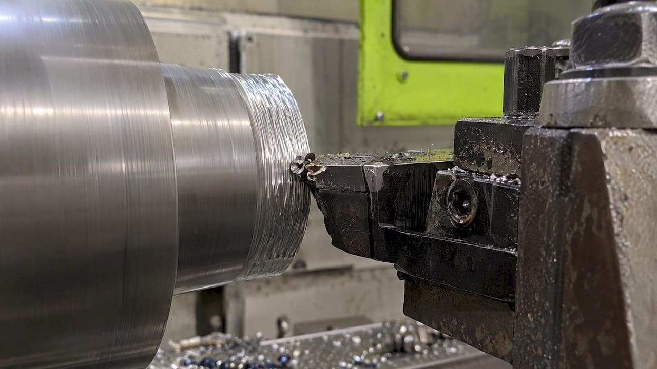
A built-up edge (BUE) is an accumulation of workpiece material that welds onto a cutting tool's rake face during machining, forming a temporary, unstable replacement for the actual cutting edge. Once it takes hold, it changes the tool's real geometry, degrades surface finish, and shortens tool life, and the fix usually comes down to adjusting cutting speed, coatings, coolant, or insert geometry.
TL;DR:
- BUE forms most readily below roughly 80 to 150 meters per minute, although the threshold varies by alloy and cutting conditions.
- BUE layers can reach several hundred micrometers, shifting rake and clearance angles; torn fragments may embed in parts, distort dimensions, or chip the cutting edge.
- Confirm suspected BUE by pairing force or spindle load spikes with torn chips, embedded surface fragments, or dimensional drift; spikes alone may indicate chatter.
- Raise cutting speed first when equipment and material permit, then test coated carbide, coolant, or sharper positive geometry one change at a time.
- A thin, stable BUE can sometimes shield a tool from abrasive wear, but production setups should not depend on that temporary protection.
How does built-up edge form at the tool-chip interface?
BUE starts with simple adhesion. As the chip slides across the rake face under extreme pressure and friction, a thin layer of workpiece material sticks to the tool, work-hardens, and welds in place. That layer then grabs the next layer of chip material, and the edge grows outward in stages rather than all at once.
Certain conditions make this far more likely:
- Low cutting speeds give adhered material time to weld and harden before it gets sheared away.
- Ductile, adhesive materials, including many stainless and low-carbon steels, bond to tool surfaces more readily than brittle ones.
- High contact pressure at the tool-chip interface accelerates local welding and work hardening.
Research summarized on Wikipedia's built-up edge entry points to BUE forming most readily at low cutting speeds, with critical thresholds often falling below roughly 80 to 150 meters per minute depending on the alloy. The edge does not grow forever: it builds, tears away in fragments, and rebuilds in a repeating cycle that defines much of the instability machinists see downstream.
What does BUE do to cutting forces, finish, and tool life?
The build-and-tear cycle shows up directly in the numbers coming off the spindle. As BUE grows and breaks away, cutting forces fluctuate rather than holding steady, and that fluctuation is often the first measurable sign something is wrong before a part ever gets inspected.
BUE layers can reach thicknesses of several hundred micrometers before tearing off, according to Zy Diamond Tools' explainer on built-up edge, which is large enough to meaningfully alter the tool's effective rake angle and clearance while it is attached. When fragments tear free, some get pressed into the workpiece surface, leaving embedded debris and a rougher, less consistent finish than the program called for. Dimensional drift follows: as the effective edge geometry shifts, the actual depth of cut and clearance change with it, and in harder cases, pieces of the tool's actual edge can chip out along with the built-up material.

There is a narrow exception worth noting. A thin, stable BUE can occasionally act as a sacrificial layer that shields the tool from abrasive wear, as described by the PMPA's guide to built-up edge. That protection is rarely reliable enough to plan around in production work, so it is a tradeoff to recognize rather than a strategy to chase.
How do you detect and confirm BUE during a job?
Catching BUE early saves a scrapped run. Most of the signs are visible or measurable without any special equipment, and a few targeted checks will confirm what you are looking at.
- Examine chip color, shape, and underside texture for rough, torn, or discontinuous sections that suggest material tearing rather than clean shearing.
- Check the part surface for shiny, embedded fragments or a sudden jump in measured roughness partway through a run.
- Watch spindle load, cutting force, or vibration readouts for repeating spikes that do not match programmed feed changes.
- Track dimensions across a run for drift that correlates with the force fluctuations rather than tool wear alone.
- When the cause is unclear, send a sample for microscopy or SEM imaging to confirm adhered layers and distinguish BUE from ordinary abrasive wear.
If force spikes show up without any of the surface or chip symptoms, it is worth ruling out chatter first. Our guide to fixing milling chatter in prototype work covers the vibration-driven instability that can look similar on a force graph but needs a different fix.
How do you prevent and manage built-up edge in the shop?
Start with cutting parameters before touching anything else. Raising cutting speed moves the process out of the low-speed window where BUE forms most readily, though it is not a universal fix. Tuning feed rate and depth of cut alongside speed often matters just as much, since contact pressure and heat generation both play into adhesion.
- Raise cutting speed first where the tool, machine, and material allow it, since BUE is most common at low speeds.
- Switch to coated carbide inserts (PVD or CVD) with a defect-free coating structure, since tribology testing on tool steels found that low-defect coatings reduced BUE while some electrolytic coatings promoted it, according to research published in Problems of Tribology.
- Adjust coolant strategy: flood coolant, high-pressure directed streams, MQL, or cryogenic delivery each change how much heat and friction build at the interface, and the right choice depends on the alloy and operation.
- Review insert geometry, including chipbreaker placement, edge radius, and rake and relief angles, since sharper, more positive geometries generally resist adhesion better than blunt or heavily honed edges.
- Make one change at a time and track the result, since speed, coating, and coolant adjustments interact and testing them together muddies which one actually worked.
Stainless alloys deserve particular attention here, since their work-hardening behavior makes them especially prone to BUE. Our shop guide to machining stainless steel walks through speed and tooling choices specific to those grades. On the coolant side, this partner guide to coolant selection for mixed metal shops is a useful reference when a shop runs both ferrous and non-ferrous jobs through the same equipment.
Pro Tip: Log your cutting speed, feed, and coolant setting every time you change one during a BUE troubleshooting run. It is the fastest way to find which variable actually fixed it.
What have we learned running short production jobs with BUE-prone metals?
Short-run and prototype work puts us in front of BUE-prone materials often enough to know which combinations tend to misbehave. Stainless and some gummy aluminum tempers are the usual suspects, and coated carbide tooling paired with a speed bump out of the low-speed range is typically our first move before anything else changes.
When a job shows symptoms like these, providing a few details speeds up the quoting process:
- Exact alloy and temper designation, since "stainless" or "aluminum" alone understates real differences in adhesion behavior.
- Current cutting parameters: speed, feed, depth of cut, and coolant method in use.
- Photos of the chip, the part surface, and any visible tool wear.
- Any force or vibration data already logged from the machine.
From there, we weigh surface finish against cycle time differently for a one-off prototype than for a production run, since a prototype can often tolerate a slower, safer pass that a production quote cannot.
Our take on chasing surface finish versus keeping the spindle moving
Perfect finish and fast cycle times pull in opposite directions when BUE is in play, and chasing both at once usually means neither import gets done well. A practical approach is to identify the speed and coolant window that keeps a given alloy out of the BUE-prone range first, then optimize feed and depth of cut inside that window rather than fighting the material at a speed where adhesion is already working against the process.
— Drake
Need a shop to troubleshoot or run your BUE-prone parts?
If a job keeps producing poor finish, drifting dimensions, or chipped edges no matter how you adjust your own setup, sending it to a shop that machines parts daily is often faster than continuing to iterate alone. We machine prototypes, short-run production parts, and fixtures, brackets, and support parts, with direct access to the machinist handling your job for quick back-and-forth on parameters.

When requesting a quote, include:
- Material, grade, and temper for the part in question.
- Current cutting parameters and any force, vibration, or finish data you have collected.
- Photos of chips, surface condition, or tool wear if BUE is suspected.
We also sell a ready-made E2 Kickstand for the KTM SX-E 2, GASGAS MC-E 2, and Husqvarna EE 2 as an example of the finish and tolerance control we hold on in-house parts. For a quote on your own job, visit our services page to get started.
FAQ
What is a built-up edge?
A built-up edge is workpiece material that welds onto a cutting tool's rake face during machining, forming a temporary and unstable edge in place of the tool's actual cutting edge. It typically forms under high friction and pressure at low cutting speeds, as described in Zy Diamond Tools' overview of BUE.
What is a built-up edge chip?
A built-up edge chip refers to a chip formed while a BUE is present on the tool, often showing a rougher, torn, or discontinuous underside compared to chips cut with a clean edge. These chips are one of the earliest visible signs that BUE has formed during a cut.
What are three types of chip formation?
Chip formation is commonly grouped into continuous chips, discontinuous chips, and built-up edge chips, each tied to different material behavior and cutting conditions. Ductile materials cut at higher speeds tend to form continuous chips, while BUE chips form when adhered material periodically tears away during the cut.
What are continuous chips in machining?
Continuous chips are long, unbroken ribbons of material produced when ductile metals are cut smoothly without significant adhesion or fracture at the tool edge. They generally indicate stable cutting conditions, in contrast to the fragmented, torn chips associated with built-up edge.
Sources
- What is Built Up Edge (BUE) and How Can You Prevent It? | Zy Diamond Tools
- Built-up edge — Wikipedia
- Adhesive built-up edge on tool steels due to friction and wear — Problems of Tribology