
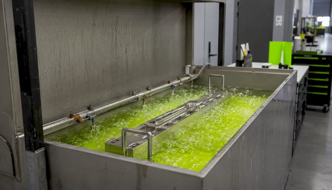
Electropolishing is a controlled electrochemical material removal process that simultaneously smooths the surface and enriches the passive layer of stainless steel. Specify it when your part needs lower surface roughness (Ra), better corrosion resistance, improved cleanability, or reduced bacterial adhesion — outcomes that mechanical polishing and chemical passivation alone cannot reliably deliver together.
Specify electropolishing when your part falls into one of these categories:
- Food processing and dairy equipment where cleanability and CIP cycle performance are critical
- Pharmaceutical and biotech components governed by ASME BPE surface finish classes
- Medical implants and surgical instruments requiring low Ra and high pitting resistance
- High-purity fluid systems and hygienic piping where contamination control is non-negotiable
- Cosmetic or decorative surfaces where a bright, reflective finish is the deliverable
- Fatigue-critical springs and thin-section parts where surface stress risers must be removed
How does electropolishing stainless steel actually work?
The mechanism is anodic dissolution: the workpiece becomes the anode in an electrolytic cell, and metal ions dissolve preferentially from surface peaks rather than valleys. The result is a smoother, more passive surface — not just a cleaner one.
The viscous-layer model explains why peaks dissolve faster than valleys. At the anode surface, a thin, high-viscosity film forms from dissolved metal salts and electrolyte products. Ion transport through this film is diffusion-limited. Because surface peaks protrude into the bulk electrolyte, they experience thinner local film thickness and faster ion transport, so they dissolve at a higher rate. Valleys sit deeper in the film, dissolve more slowly, and the net effect is leveling rather than uniform etching.
At the same time, the passive oxide layer is stripped and rebuilt continuously during the process. The rebuilt layer is thicker and richer in chromium oxide than the original, which is why electropolished stainless steel shows improved corrosion resistance beyond what mechanical polishing can achieve.
Gas evolution runs at both electrodes: oxygen at the anode (workpiece) and hydrogen at the cathode. Oxygen bubbles clinging to the anode surface interrupt current flow locally, which is the primary cause of gas-trail streaking defects. Cathode hydrogen is less of a surface concern but creates ventilation and explosion risks that shop design must address.
Keep in mind that electropolishing removes only a thin layer within a very narrow range specified by NASA PRC-5009. Deep scratches, laps, seams, and non-metallic inclusions will not be hidden — they will be highlighted. Mechanical finishing must be complete before the part enters the tank.
Pro Tip: Orient parts so that gas bubbles rise freely off the surface and exit without traveling across a finished face. Tilt flat panels at 15–30° from vertical, and position the longest dimension vertically. This single fixturing decision eliminates most gas-trail complaints before they start.
Key mechanism points:
- Anode: workpiece (stainless steel part)
- Cathode: typically 316L stainless or lead plate
- Electrolyte: hot phosphoric/sulfuric acid mixture
- Smoothing driver: diffusion-limited dissolution through the viscous salt film
- Passivation driver: continuous oxide stripping and chromium-enriched regrowth
What process parameters control the electropolishing result?
Current density, temperature, and time interact as a system. Change one without adjusting the others and you shift the process outside its window, from smoothing into etching or burning.
The IMOA/Euroinox reference places the operating envelope for stainless steel at 40–75°C and 5–25 A/dm². Within that envelope, higher current density accelerates material removal and can improve gloss, but it also raises heat input and gas evolution — both of which cause defects if not controlled. Lower temperature slows the process and narrows the window where smoothing dominates over etching.
Research on AISI 316L published in Materials (MDPI) found that approximately 35°C and 8 A/dm² gave the best balance of surface finish and material removal in both lab and scaled tests. That is cooler than many production baths run, which is worth noting when you are dialing in a new setup.
| Parameter | Typical range | Effect of increasing | Effect of decreasing |
|---|---|---|---|
| Temperature | 40–75°C | Faster removal, more gas, risk of burning | Slower, narrower window |
| Current density | 5–25 A/dm² | More gloss, higher removal, more heat | Slower leveling, risk of etching |
| Time | 5–30 min | More removal, risk of over-etching | Incomplete leveling |
| Water content | 10–20 wt% | Lower viscosity, etching tendency | Higher viscosity, slower dissolution |
| Iron load | 0–30 g/L | Stabilizes bath (to a point) | Unstable new bath, variable results |
Bath aging is a real process variable. As iron dissolves from parts, Fe²⁺ concentration builds in the bath. A fresh bath with no iron load gives inconsistent results; Leuze Verlag recommends pre-loading a new bath with approximately 30 g/L of iron (by dissolving scrap steel) to reach stable operating chemistry before running production parts. Once iron exceeds recommended levels, bath performance degrades and partial replacement is needed.
Hull cell tests are the right tool for dialing in a new bath or recovering a drifting one. Run a Hull cell panel before committing production parts, and map the current-density gradient against the surface result to confirm you are operating in the leveling zone.
Pro Tip: When scaling from a lab cell to a production tank, reduce current density by 15–25% from your lab-optimized value as a starting point. Larger surface areas mean more total gas evolution and more heat accumulation. The Metals (MDPI) scale-up study documents exactly this: lab-optimized parameters caused surface defects on industrial parts due to gas evolution and overheating.
Which stainless grades respond well, and which cause problems?
The 300-series austenitics — 304, 316, and 316L — are the best candidates for electropolishing. Their homogeneous, single-phase microstructure dissolves uniformly, and the process reliably produces bright, smooth surfaces with enriched passive layers. The British Stainless Steel Association (BSSA) confirms that most stainless alloys can be electropolished successfully, with typical material removal of 0.0002–0.0005 in (5–13 µm) per surface, matching the requirements in NASA PRC-5009.
Problematic grades and situations:
- Sulfurized free-machining grades (e.g., 303): Manganese sulfide inclusions dissolve preferentially, leaving pits and a rough, uneven surface. The BSSA explicitly flags these as poor candidates. If your drawing calls for 303 and a polished finish, change the alloy or accept a mechanical-only finish.
- High-carbon martensitic grades (e.g., 440C): Carbide networks at grain boundaries dissolve at different rates than the matrix, producing a mottled or etched appearance. Stress-relief heat treatment before EP reduces cracking risk on temper-sensitive grades.
- Duplex stainless steels: The two-phase microstructure (austenite + ferrite) dissolves at different rates. Results are possible but require tighter parameter control and are less predictable than with pure austenitics.
- Complex internal cavities and blind holes: Electrolyte circulation and current distribution are uneven inside deep bores or narrow channels. EP on internal surfaces requires specialized tooling or flow-through fixtures; standard tank immersion will not reach them uniformly.
Pre- and post-treatment requirements by grade:
- 304/316/316L: clean, degrease, and remove all mechanical finishing residue; nitric acid rinse post-EP to remove smut
- Martensitic grades: stress-relief anneal before EP; verify hardness is within spec before processing
- Any grade with weld scale: pickle first to remove heat-affected zone oxide; EP after pickling, not instead of it
- Parts with tight tolerances: confirm dimensional allowances account for typical material removal before committing to EP
For heat treatment and stress-relief considerations on sensitive alloys, the same logic that applies to aluminum temper selection before machining applies here: the metallurgical state of the part going into the finishing process determines the outcome.
What equipment do you need to electropolish at shop scale?
The choice between a bench system and a rack/tank production line comes down to part size and volume. Bench systems handle small parts and prototypes; rack/tank systems are required for anything larger than about 12 inches in any dimension or for runs above a few dozen parts per shift.
Core equipment list:
- Tank: Polypropylene or PVDF-lined steel, sized to allow full part immersion with clearance on all sides. Heating elements must be acid-resistant (PVDF or titanium-sheathed).
- Rectifier: DC power supply with voltage and current control. Size for peak current demand: total surface area (dm²) × maximum current density (A/dm²). Add 20% headroom for bath variation.
- Cathodes: 316L stainless plate, sized to provide uniform current distribution. Cathode-to-anode area ratio of 2:1 to 3:1 is a common starting point.
- Pumps and filtration: Recirculation pump to maintain bath uniformity and temperature; filter to remove particulates that cause pitting.
- Drag-out tank: Rinse tank immediately after the EP tank to recover dragged-out acid, reduce waste treatment load, and protect the rinse water quality.
- Exhaust ventilation: Local exhaust directly over the tank surface, sized for the acid mist load. This is a regulatory requirement, not optional.
Fixturing and masking considerations:
- Titanium or 316L stainless fixtures resist the bath and maintain conductivity. Copper and brass corrode rapidly and contaminate the bath.
- Contact points must be clean and tight. High-resistance contacts cause local burning and uneven removal.
- Mask features that must hold tight tolerances or threads using acid-resistant tape (PTFE) or stop-off lacquer. Confirm the masking material's acid resistance before use.
- For dimensional verification of threaded features after EP, go/no-go gauges are the fastest way to confirm that material removal stayed within tolerance.
Throughput drivers: cycle time (typically 10–20 minutes in the bath), plus load/unload, rinse, and dry time. A single-tank bench system can realistically process 15–25 small parts per shift with one operator. Production rack systems with automated transfer can multiply that by an order of magnitude.
How do you inspect and accept an electropolished surface?
Check these immediately after EP and before parts leave the shop:
- Copper sulfate test: — A quick field test for passive layer quality. A properly electropolished 316L surface will not show copper deposition after 6 minutes of contact per ASTM A380.
- Dimensional check: — Verify that material removal stayed within the allowable range. NASA PRC-5009 specifies 0.0002–0.0005 inch per surface as the acceptable removal window. For tight-tolerance features, measure before and after EP.
Qualification coupons are mandatory for new part numbers and new bath setups. Run coupons of the same alloy and surface condition alongside the first production lot, and retain them for traceability. NASA PRC-5009 requires this explicitly, and it is good practice regardless of whether your customer is NASA.
Cost drivers, throughput, and how to write an electropolish spec
The primary cost drivers are rectifier energy, cycle time, bath maintenance (chemical replenishment and disposal), and fixturing/masking labor. For prototype and short-run work, fixturing labor often dominates because each new part geometry requires a custom fixture design.
Throughput considerations:
- Typical EP cycle time: 10–20 minutes in the bath for most stainless parts
- Total cycle time including load, rinse, dry, and inspect: 45–90 minutes per rack for a manual bench system
- Bath maintenance adds roughly 10–15% overhead to total process time when monitored properly
- Masking complex geometries can add 30–60 minutes per part for the first article
Drawing note language (sample):
For surface finish spec guidance on other finishing processes, the same principle applies: state the standard, the removal limit, the acceptance criterion, and the test method. Vague notes like "electropolish, bright finish" leave too much to interpretation and generate RFIs.
What vendors will ask when quoting:
- Alloy and condition (304, 316L, annealed, hardened?)
- Starting Ra and required final Ra
- Part geometry: flat, tubular, complex? Internal surfaces?
- Masking requirements
- Applicable standard (ASTM B912, NASA PRC-5009, ASME BPE class?)
- Lot size and frequency
- Required test documentation (Ra report, copper sulfate, potentiodynamic?)
The NASA PRC-5009 specification is the most complete publicly available process specification for electropolishing of corrosion-resistant steel. Even if your application is not aerospace, it is worth reading before you write your first drawing note.
Recommended starting parameters for 316L: a shop-backed window
For 316L stainless steel, the literature-backed starting window that balances surface finish, material removal, and process stability is: 35°C bath temperature, 8 A/dm² current density, 15–20 minutes, phosphoric/sulfuric acid bath (approximately 45/35 wt% with 20% water). This window comes from the MDPI Materials study on AISI 316L, which found this combination gave superior results in both lab and industrial-scale tests, and aligns with the practical formulation guidance from Leuze Verlag.
| Parameter | Recommended starting value | Acceptable range | Notes |
|---|---|---|---|
| Bath temperature | 35°C | 30–45°C | Higher temps increase defect risk at scale |
| Current density | 8 A/dm² | 6–12 A/dm² | Reduce 15–25% when scaling to production |
| Time | 15–20 min | 10–30 min | Adjust based on starting Ra and removal target |
| H₃PO₄ concentration | ~45 wt% | 40–50 wt% | Per Leuze Verlag formulation |
| H₂SO₄ concentration | ~35 wt% | 30–40 wt% | Per Leuze Verlag formulation |
| Iron pre-load | ~30 g/L | 20–40 g/L | Pre-load new bath before production runs |
| Expected removal | 0.0002–0.0005 in (5–13 µm) | Per NASA PRC-5009 | Verify dimensionally on first article |
Shop qualification checklist for a new 316L setup:
- Prepare three coupons of the same alloy heat and surface condition as the production part
- Set rectifier to target current density; verify with a calibrated clamp meter, not the rectifier display
- Run a Hull cell panel to confirm the bath is in the leveling zone before committing coupons
- Process coupons at the target parameters; measure Ra before and after with a contact profilometer
- Perform copper sulfate test on one coupon; retain the others for dimensional and corrosion testing
- Document bath temperature, current density, time, iron load, and pH for every qualification run
- Compare removal to the 0.0002–0.0005 in per surface window from NASA PRC-5009
- Review the BSSA electropolishing guidance and ASTM B912 before writing your internal procedure
The SAGE Journals review confirms that electropolished 316L shows measurably better pitting resistance than mechanically processed or pickled equivalents, which validates this window as a starting point for applications where corrosion performance is the primary driver.
Key Takeaways
Electropolishing stainless steel requires correct alloy selection, a stable phosphoric/sulfuric acid bath, and tightly controlled current density and temperature to deliver measurable Ra reduction, passive-layer enrichment, and improved corrosion resistance.
| Point | Details |
|---|---|
| Best alloys for EP | 304 and 316/316L respond best; avoid sulfurized free-machining grades like 303. |
| Starting parameters for 316L | 35°C, 8 A/dm², 15–20 min in a 45/35 wt% phosphoric/sulfuric bath per MDPI research. |
| Material removal window | a very small controlled thickness per surface, as specified by NASA PRC-5009; account for this in tolerances before EP. |
| Pre-load new baths | Add ~30 g/L iron to a fresh bath before production runs to stabilize chemistry. |
| Scale-up caution | Reduce current density 15–25% from lab values when moving to production tank size. |
A shop perspective on when electropolishing makes sense
Electropolishing comes up regularly at Flying Chip Factory when customers are designing parts for food-contact, pharmaceutical, or high-purity fluid applications, and when the drawing calls for both a specific Ra target and corrosion performance that passivation alone cannot guarantee. The most common scenario: a 316L prototype that needs to hit an ASME BPE surface finish class before it goes into a bioprocessing skid. The machining tolerances are tight, the Ra target is tight, and the customer needs documentation.
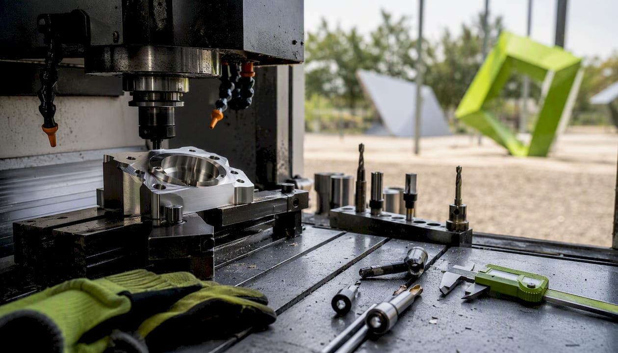
When Flying Chip Factory includes EP in a quote, the line items are explicit: fixturing design, masking for any threaded or tolerance-critical features, first-article coupon processing, Ra measurement, and copper sulfate testing. Customers should come to the table with the applicable standard (ASTM B912, NASA PRC-5009, or ASME BPE class), the required Ra, and a clear note on which features must be masked. Vague finish callouts add time and cost to every quote.
The direct-machinist communication model matters here more than most customers expect. EP decisions often surface mid-project, when a design review reveals that a mechanically polished surface will not meet the contamination spec. Being able to call the machinist directly, discuss the alloy, the geometry, and the tolerance stack, and get a revised quote the same day is the difference between a one-week delay and a three-week one. If you have a part that needs electropolishing alongside CNC machining, get in touch with Flying Chip Factory to discuss the geometry and get a quote that accounts for the full finishing sequence.

Useful sources for qualification and spec writing
These are the primary references used to build this guide. Each one serves a specific purpose in your qualification or specification workflow.
- Materials (MDPI) — Electropolishing parameters study
- Electropolishing of Stainless Steel in Laboratory and Industrial Scale — Metals (MDPI)
- Electropolishing of stainless steels — British Stainless Steel Association
- Electropolishing Stainless Steels — IMOA / Euroinox
- Electropolishing of Stainless Steel — Leuze Verlag
- Process Specification for Electropolishing of Corrosion Resistant Steel — NASA PRC‑5009
- ASTM B912 — Standard Practice for Passivation of Stainless Steels
- Electropolishing — Stainless Steel (review) — SAGE Journals