
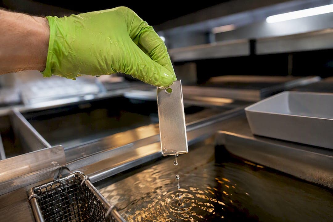
Alodine preserves electrical conductivity when it's specified and processed as MIL-DTL-5541 Class 3, not the more common Class 1A. That distinction belongs on the drawing, not left to the finisher's judgment. Class 3 gives engineers a thin, low-resistance conversion coating suited to grounding lugs, EMI gasket surfaces, and heat sink interfaces, while numeric acceptance limits and contact resistance testing confirm the part actually performs before it ships.
TL;DR:
- Proper processing of Alodine as MIL-DTL-5541 Class 3 is essential for low-resistance conductive coatings, with immersion times typically between 10 and 30 seconds.
- Coating thickness, controlled by time, temperature, and pH, determines whether the film meets Class 3 specifications or drifts into higher resistance Class 1A performance.
- Contact resistance testing under 200 psi electrode pressure must measure ≤5,000 microohm-inches squared before environmental exposure and ≤10,000 microohm-inches squared after salt spray, to ensure performance.
- Selecting the correct surface finish involves specifying Class 3 only on conductive zones and using masking to prevent unintended coatings on other areas.
- Aluminum alloy choice impacts conductivity consistency, with 6061 being most predictable, whereas higher-copper alloys require tighter process controls.
How does alodine for conductivity actually work?
Alodine is a chromate conversion coating, not a plated or sprayed finish. It reacts with the aluminum surface itself, converting a microscopic layer of the base metal into a mixed oxide and chromium compound film, rather than depositing an insulating layer on top of it. That chemical distinction is why it behaves so differently from anodize, which grows a genuinely insulating aluminum oxide layer that can run several microns thick and block electrical paths outright.
A properly processed Class 3 film measures roughly 0.01 to 0.04 micrometers thick, thin enough that it has no measurable effect on part dimensions or thread fit. At that scale, the coating doesn't behave like a continuous barrier. Surface asperities, the microscopic peaks and valleys on any machined surface, poke through or compress the film under contact pressure, giving metal-to-metal touch points that carry current. The conversion coating mechanism explained by NAMF confirms this is why conductive chem film is the standard recommendation wherever electrical continuity actually matters.
Where this shows up on real assemblies:
- Chassis grounding straps and bonding jumpers, where any resistance in the path defeats the purpose of the ground
- EMI shielding gaskets and enclosure seams, where contact resistance directly limits shielding effectiveness
- Heat sink mounting interfaces, where thermal and electrical continuity often ride on the same surface
- Connector shells and RF housings, where signal integrity depends on a low-impedance chassis return
If your drawing calls for "chem film per spec" without a class, expect variability. The type of chemistry and the immersion time both push the coating weight, and coating weight is the lever that determines whether you land in Class 3 territory or drift toward Class 1A.
What does MIL-DTL-5541 actually require for Class 3?
MIL-DTL-5541 is the governing specification for chromate and chromate-alternative conversion coatings on aluminum, and it splits performance into classes that trade off corrosion protection against electrical conductivity. Class 1A is the corrosion-priority option: a heavier, more protective film that accepts higher contact resistance in exchange for better salt spray performance. Class 3 films are thinner and tuned for low contact resistance, which is the entire point when a surface needs to conduct.
The spec also separates coating chemistry into types. Type I is the traditional hexavalent chromium process, still used where legacy qualification requires it. Type II covers trivalent chromium, commonly branded TCP (trivalent chromate pretreatment), and gives most new programs a RoHS-compliant path to Class 3 performance without the regulatory overhead of hexavalent chromium handling.
MIL-DTL-5541 Class 3 numeric limits: Contact resistance must measure ≤5,000 microhm-inches squared as supplied, and ≤10,000 microhm-inches squared after 168 hours of salt spray exposure, with both measurements taken under 200 psi of electrode pressure. Those two numbers, plus the test pressure, are the entire acceptance criteria for a conductive Alodine callout.
A tight spec callout should include:
- The standard: MIL-DTL-5541
- The class: 3 (conductive) or 1A (corrosion)
- The type: I (hexavalent) or II (trivalent/TCP)
- The required tests: contact resistance as-supplied and post-salt-spray, with electrode pressure noted
Drop any one of those four elements and you're relying on the finisher's default process, which may or may not land where you need it.
Which process variables actually control conductivity?
Coating weight is the variable that decides whether a part meets Class 3 or drifts into Class 1A territory, and coating weight is controlled almost entirely by time, temperature, and pH at the tank.
- Immersion time. Shorter dwell times, typically in the 10 to 30 second range, produce the thinner films Class 3 requires. Push immersion longer and the coating thickens, contact resistance climbs, and you end up with something closer to Class 1A performance whether you specified it or not.
- Bath temperature and pH. Most conversion coating processes run in a narrow temperature and pH window; drift outside it and coating weight becomes inconsistent from part to part, even within the same batch.
- Rinse quality. Poor rinse conductivity after the conversion tank leaves residual salts on the surface, which can skew contact resistance readings independent of the actual coating performance.
- Surface roughness and electrode flatness. Rougher surfaces and fractured films often measure lower resistance under high electrode pressure than a smooth, uniform coating would, because the peaks punch through the thin film more readily. That means two parts with identical coating chemistry can post different contact resistance numbers purely because of finish. Check the surface finish chart for Ra, RMS, and Rz conversions before setting a spec that assumes a specific starting roughness.
- Alloy selection. 6061 aluminum is a common and forgiving substrate for Class 3 chem film, with predictable, repeatable conductivity results in production. Higher-copper alloys like the 2000 series can behave less predictably and may need tighter process control to hit the same numbers.
Pro Tip: If a supplier's process sheet doesn't list immersion time as a controlled variable, ask for it. That single number tells you more about whether you'll land in Class 3 spec than almost anything else on the traveler.
Bath chemistry additives, including surfactants and pH buffers, also affect how evenly the coating forms across a part. Formulation suppliers like ASTRA CHEMICAL offer the kind of dispersants and leveling agents that finishing shops use to keep conversion baths consistent batch to batch.
How do you test and verify conductive Alodine performance?
Contact resistance testing is the only way to confirm a Class 3 finish actually performs, and the method matters as much as the number. Test fixtures apply a fixed electrode pressure, normalized at 200 psi in the MIL-DTL-5541 method, across a defined contact area, then measure resistance and report it in microhm-inches squared. That normalization exists because resistance readings shift with pressure, electrode flatness, and contact area, so an uncontrolled test setup produces numbers that don't mean anything against the spec.
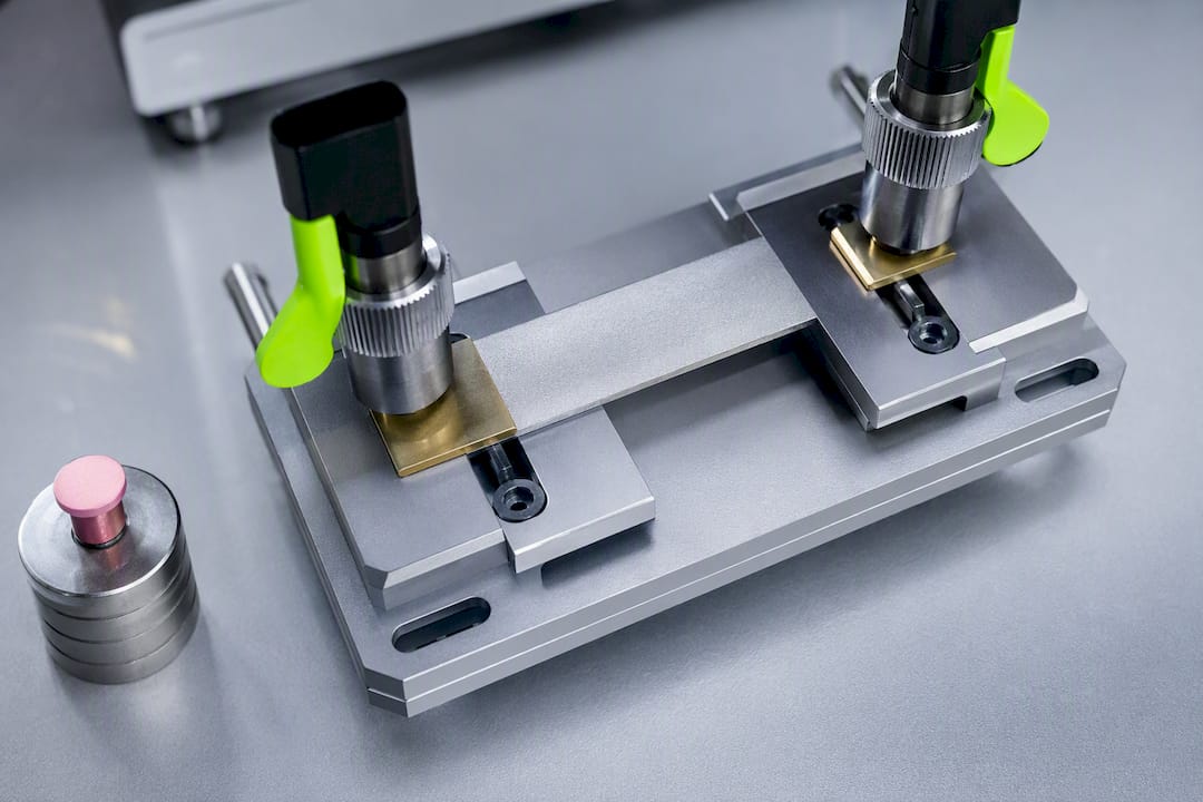
MIL-DTL-5541 Class 3 acceptance: ≤5,000 µΩ/in² as supplied; ≤10,000 µΩ/in² after 168 hours of salt spray exposure, both at 200 psi electrode pressure.
Verification typically covers three checks:
- As-supplied contact resistance, run before the part sees any environmental exposure
- Post-salt-spray contact resistance, run after the 168-hour exposure to confirm the coating hasn't degraded to the point of failing electrically
- Functional continuity checks, including grounding path resistance and EMI shielding effectiveness once the part is in assembly, which catch failures that a coupon test alone might miss
A finish that fails as-supplied but passes post-salt-spray (or the reverse) usually points to inconsistent coating weight across the batch rather than a chemistry problem. Testing both is the only way to catch that. If a part fails, remediation options include stripping and reprocessing, localized touch-up on specific contact zones, or adding a mechanical bonding strap where the coating alone can't be trusted to carry the return path. Masking critical surfaces before a secondary finish, or during rework, follows the same 12 to 24 hour dwell guidance used for anodize masking on CNC parts, since adhesive dwell time affects how clean the mask line comes out.
Corrosion protection vs conductivity: which finish wins?
Corrosion resistance and electrical conductivity pull in opposite directions on the same coating, and picking the wrong side of that trade-off is the single most common spec mistake on drawings.
Class 1A sits at the corrosion-resistant end. It's the right call for exterior enclosures, marine environments, or any surface that needs long-term protection and doesn't carry current. Class 3 sits at the conductivity end, giving up some corrosion margin for a film thin enough to stay electrically transparent. It's appropriate for interior electronics, grounding hardware, and EMI contact surfaces, but it is not the answer for a part facing sustained salt fog or outdoor weathering without additional protection.
Practical guidance for mixed-requirement assemblies:
- Specify Class 3 only on the functional contact surfaces (ground lugs, gasket seats, connector shells), and Class 1A or a painted finish everywhere else on the same part
- Use masking to keep the conductive zones free of paint or anodize during secondary finishing
- Watch galvanic coupling at fastener interfaces when conductive aluminum surfaces mate to steel or stainless hardware; a conductive finish that improves grounding can also accelerate galvanic corrosion if the joint isn't sealed or isolated
- For assemblies split between electronics housings and structural exteriors, treat each zone as its own finish decision rather than picking one class for the whole part
Alodine vs anodize vs plating: which finish for which zone?
Every finish decision on a precision part comes down to what that specific surface needs to do, not what the rest of the part needs.
Conductivity: Alodine Class 3 wins outright. Anodize insulates by design, and even conductive-tape workarounds on anodized parts are a maintenance liability compared to a coating that's conductive from the start. Conversion coatings preserve electrical continuity where anodize commonly breaks the grounding path, which is why anodize shows up so often as the root cause when a grounding-critical part fails inspection.
Dimensional impact: Alodine adds essentially nothing to part dimensions. Anodize can add measurable thickness that needs to be accounted for in tight-tolerance fits.
Wear and abrasion resistance: Anodize, especially hardcoat, outperforms Alodine significantly. If a surface needs to survive sliding contact or repeated handling, Alodine alone isn't the answer.
Paint adhesion: Both finishes provide a good paint base, though Alodine is frequently used specifically as a pretreatment layer under paint on parts that also need corrosion resistance.
A quick decision checklist for each functional zone on a part:
- Does this surface need to conduct? If yes, specify Class 3, Type II unless legacy qualification requires Type I chemistry.
- Does this surface face sustained corrosive exposure? If yes, consider Class 1A or a supplemental coating.
- Is dimensional tolerance tight on this feature? Alodine is dimensionally safer than anodize.
- Will this surface see wear or abrasion? Consider anodize or plating instead.
For a deeper side-by-side on finish selection logic, the Alodine vs anodize decision guide walks through spec language examples for mixed-finish drawings.
What Flying Chip Factory sees on the shop floor
The failure pattern Flying Chip Factory sees most often on incoming prototype drawings: a blanket "anodize per spec" callout on a part that also needs a grounding path. The fix documented across finishing guides matches what shows up in production. Switching the contact surface from anodize to Class 3 chem film restores continuity to milliohm-level readings without touching the part's dimensions or tolerance stack.
On incoming work, checks typically include contact resistance verification on the specific mating surfaces called out on the drawing, visual inspection for coating uniformity and any bare spots, and localized touch-up where a coating gap shows up on an otherwise-good part. When a customer sends a print without a finish class specified, the first question back is usually which surfaces carry current and which ones just need to look good and resist corrosion.
If you're sourcing a prototype or short-run job that needs Class 3 conductivity on specific surfaces, say so on the RFQ and request contact resistance data with the finished parts. That single line on a quote request saves a round of rework almost every time.
Specify the finish before you cut metal
Get the finish class into the design review before parts hit the CNC, not after a grounding failure shows up in final assembly. Rework on a part that already has holes drilled and threads cut costs real time, and it's avoidable with one line on the drawing.
Push back if a finisher defaults to "standard chem film" without confirming class and type, and always ask for as-supplied contact resistance data before parts ship, not just a certificate of conformance. If conductivity matters anywhere on the assembly, get the finishing conversation started at the same point you're locking tolerances, not after the first article comes back from inspection.
— Drake
Get Class 3 Chem Film Handled Right From the Start
Most shops treat finish specification as an afterthought, something to sort out after the part is already cut. Flying Chip Factory builds it into the quote conversation from the start, because a grounding surface that fails contact resistance testing after machining is a rework job nobody wants. Prototype machining, short-run production, and fixture or bracket fabrication all run through direct communication with the machinist who's actually cutting the part, so a Class 3 Alodine callout with specific test requirements doesn't get lost in translation between sales and the shop floor.

That same attention to fit and function shows up in Flying Chip Factory's own products. The E2 Kickstand for KTM SX-E 2, GASGAS MC-E 2, and Husqvarna EE 2 electric mini dirt bikes is CNC-machined in-house with the same fit-first approach applied to every customer job. If your next part needs a documented conductive finish, request a quote directly with the machinist and specify the class, type, and test requirements up front.
Sources
- MIL-DTL-5541F Chemical Conversion Coatings on Aluminum and Aluminum Alloys
- Contact resistance — MIL-DTL-5541 testing guidance (ATSLab)
- Alodine Process: Aluminum Finish Selection & Specification Guide
- How Alodine Coating Works on Aluminum
FAQ
Is Alodine electrically conductive?
Yes, when processed as MIL-DTL-5541 Class 3, Alodine remains electrically conductive because the film is thin enough for surface asperities to maintain metal-to-metal contact. Class 3 parts must measure ≤5,000 µΩ/in² as supplied and ≤10,000 µΩ/in² after 168 hours of salt spray at 200 psi electrode pressure.
Which alloy is best for electrical conductivity with Alodine?
6061 aluminum is a common, forgiving substrate for Class 3 chem film and tends to produce consistent contact resistance results in production. Higher-copper alloys can behave less predictably and may need tighter process control to hit the same numbers reliably.
Does anodizing aluminum make it less conductive?
Yes, anodizing grows an insulating oxide layer that commonly breaks grounding and EMI paths entirely. Conversion coatings like Alodine preserve conductivity where anodize does not, which is why grounding-critical surfaces should be specified as chem film rather than anodize.
How long do you leave Alodine on aluminum?
For Class 3 conductive film, immersion times typically run 10 to 30 seconds, producing a thinner coating tuned for low contact resistance. Longer immersion times build a heavier film that trades conductivity for corrosion resistance, pushing performance toward Class 1A instead.
Can Flying Chip Factory finish parts to Class 3 Alodine specifications?
Flying Chip Factory accepts Class 3 Alodine specifications on prototype and short-run machining jobs, with contact resistance verification available on request. Note the required class, type, and test parameters on your RFQ through the services page to confirm capability and timeline for your specific part.